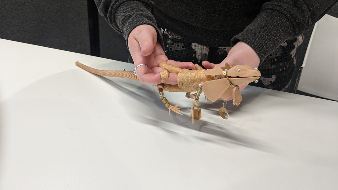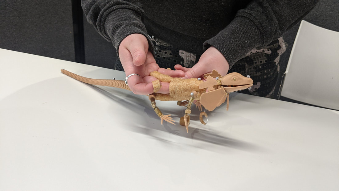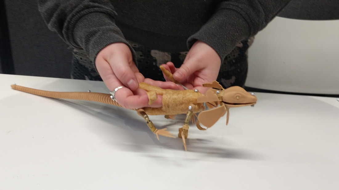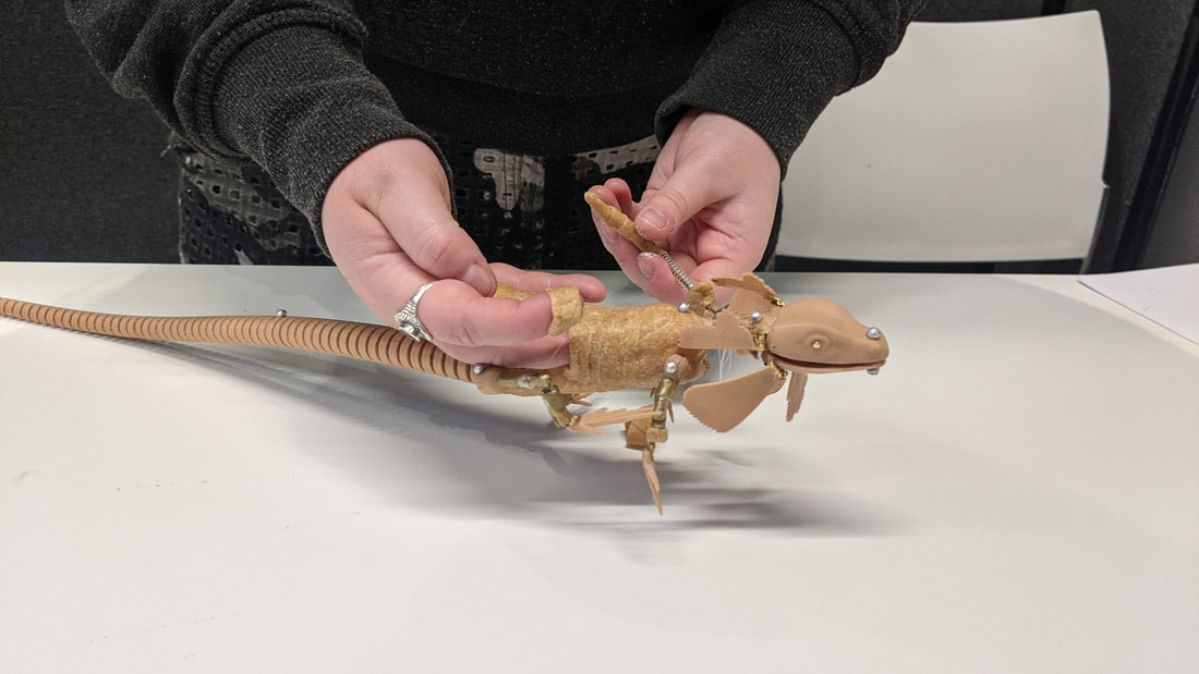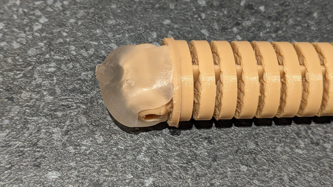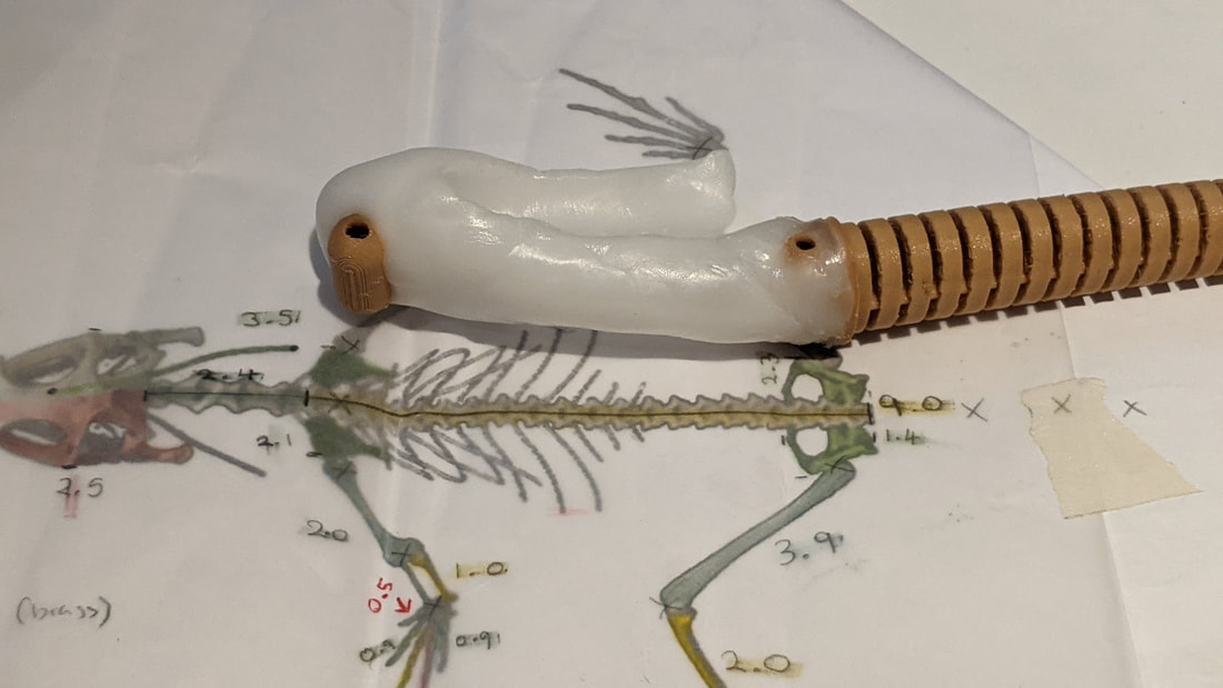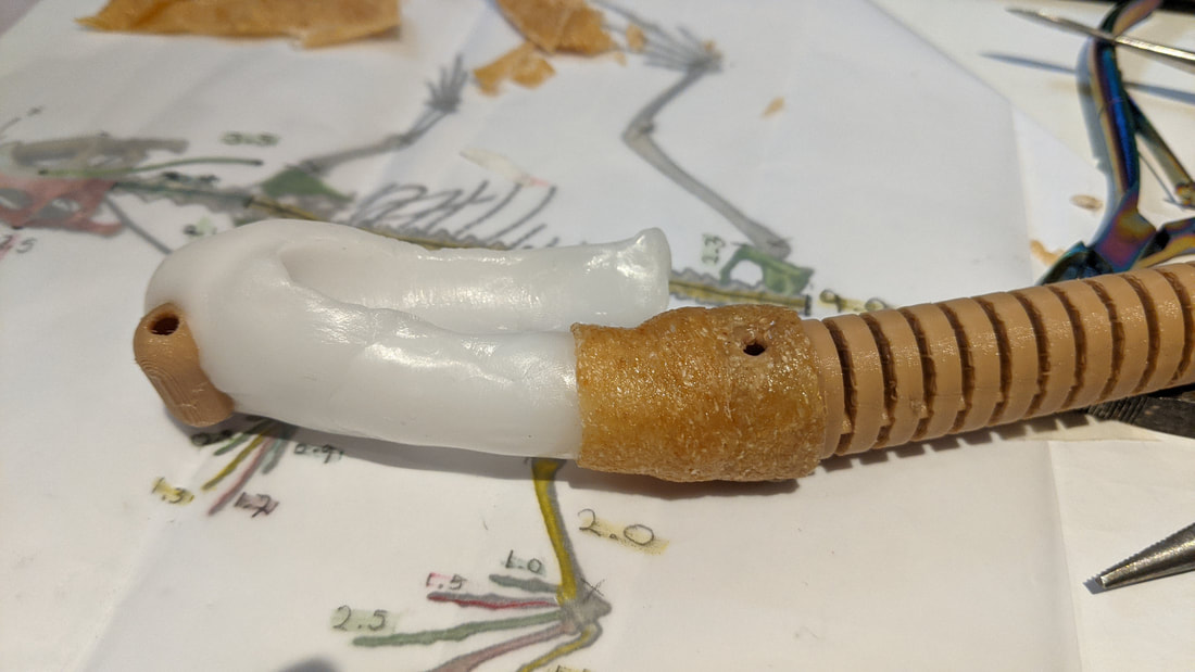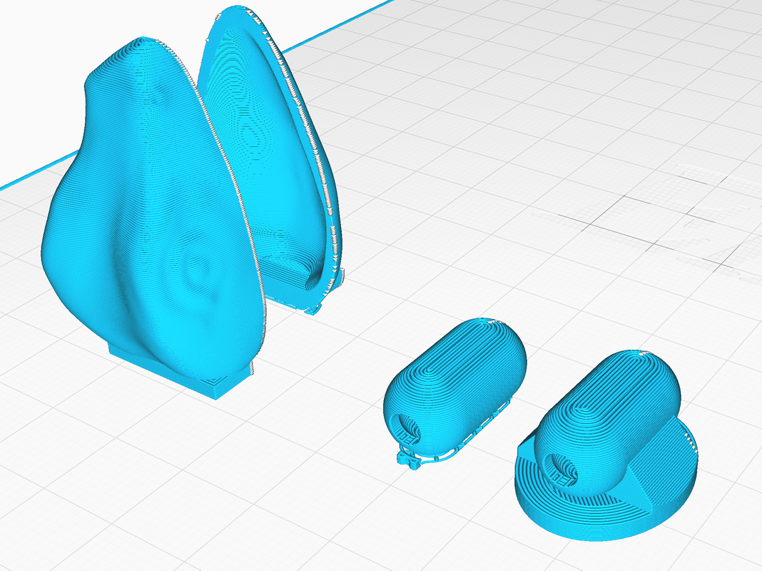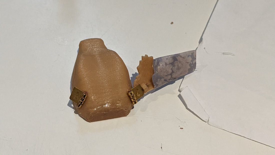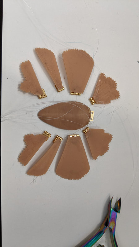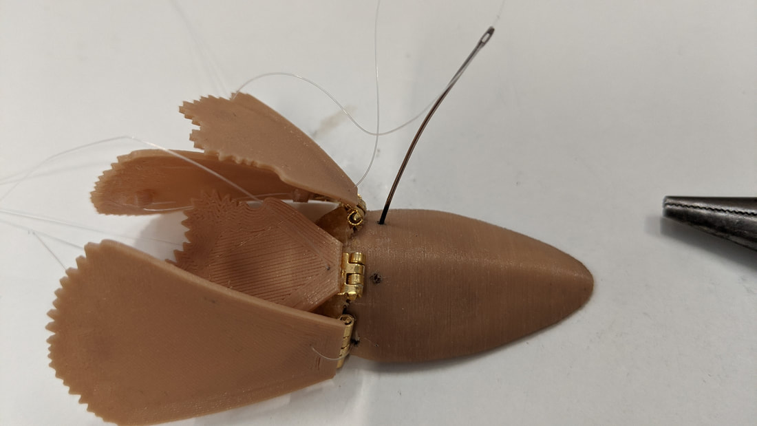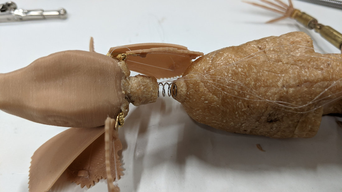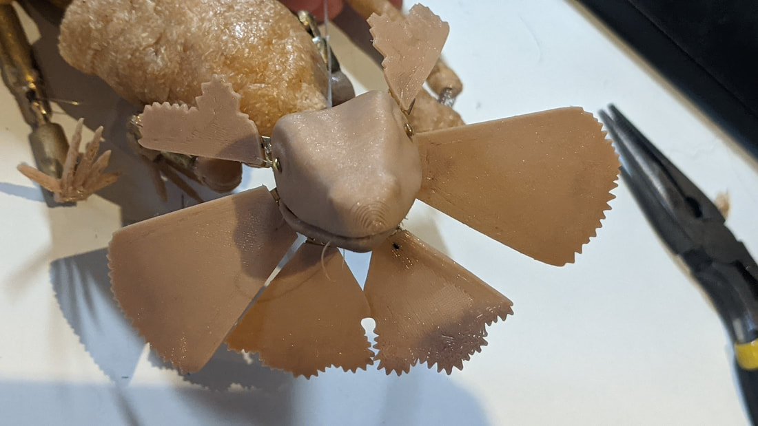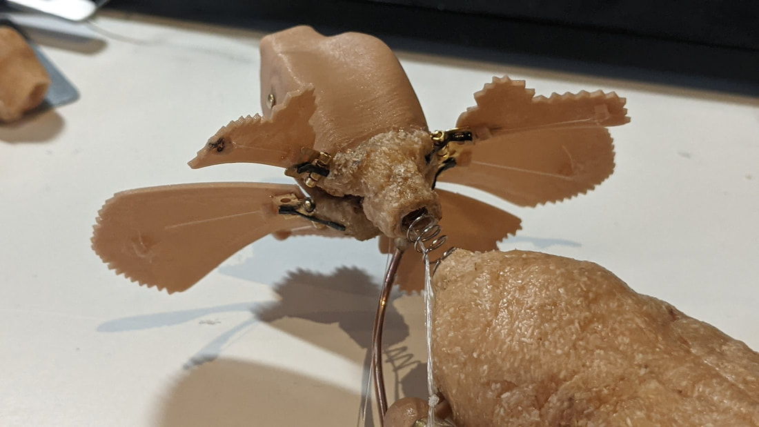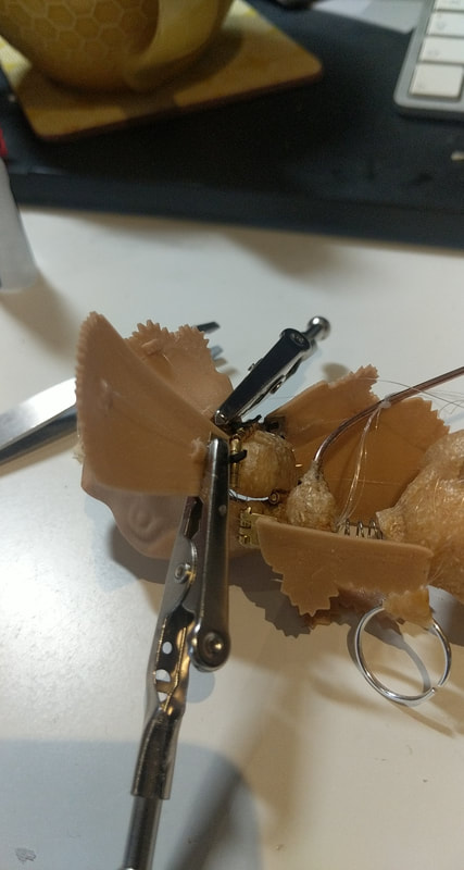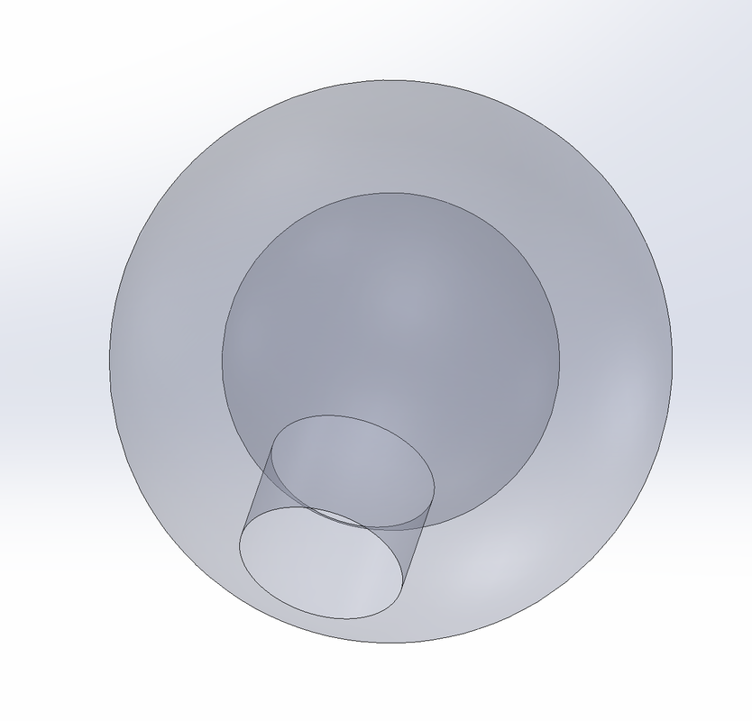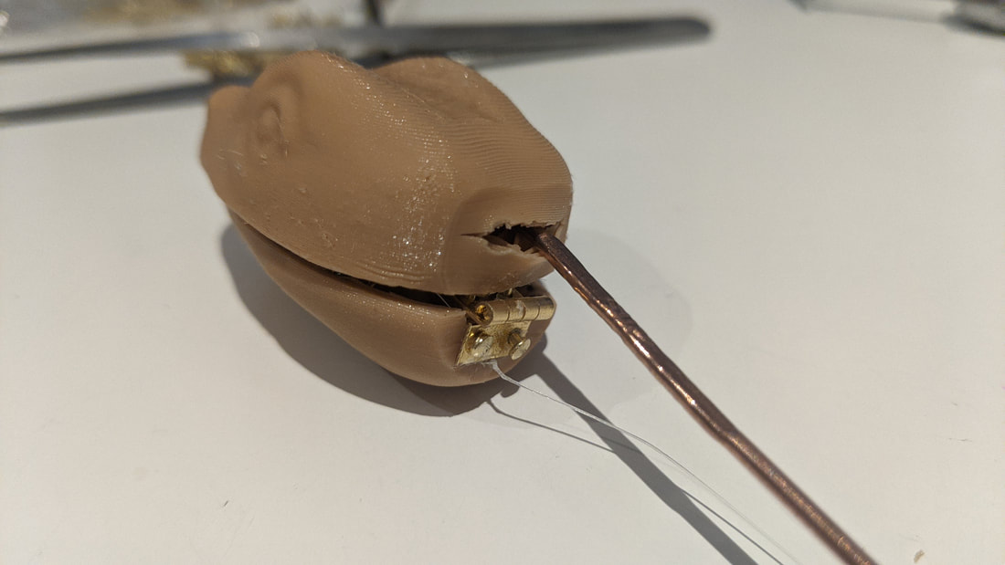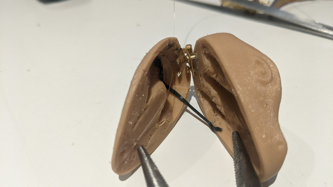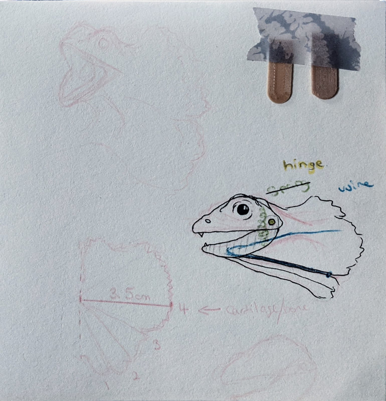
BodyWorking on the lizard main body part; polymorph but a smaller amount. Also pictured are the final shoulder and hip sockets - they are the same as the sphere previously made but mirrored and the hips include a simple disk for the tail to glue into place. These integrated perfectly with the two thermoplastics using a heat gun and soldering iron to melt and mould the materials. The Worbla was a great choice not only due to its natural sandy colour but also as it can be heated and moulded to the shape of my hand. Neck FrillsOnce the body was complete I moved onto attacking the head with a spring and began the process of attaching the head frills. Each needed its own hinge and a strand of fishing wire leading through the head and down out the neck. MechanismsThis was the hardest part of the model as getting tensions right while not compromising movement was always a struggle. I like the spring addition to the head control stick - I went with this two handed design to maximise control over the puppet. Things to note about my progress here:
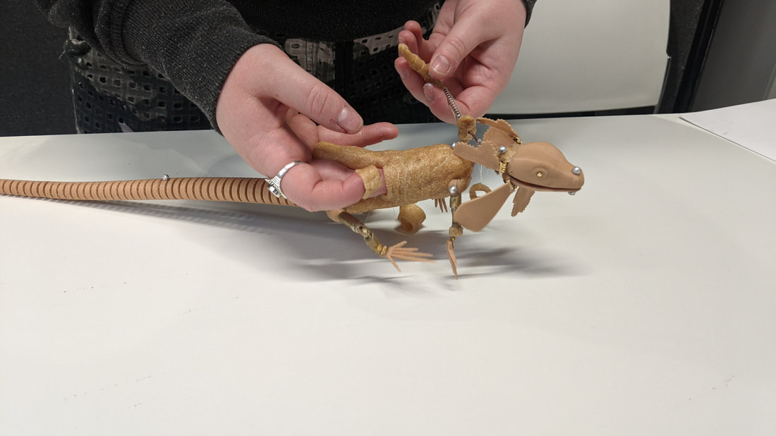
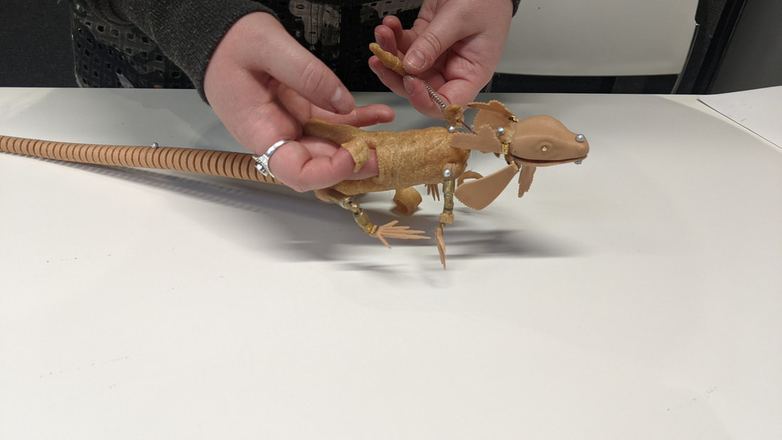
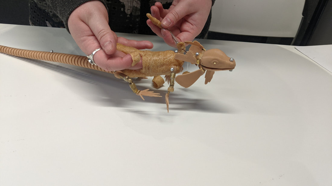
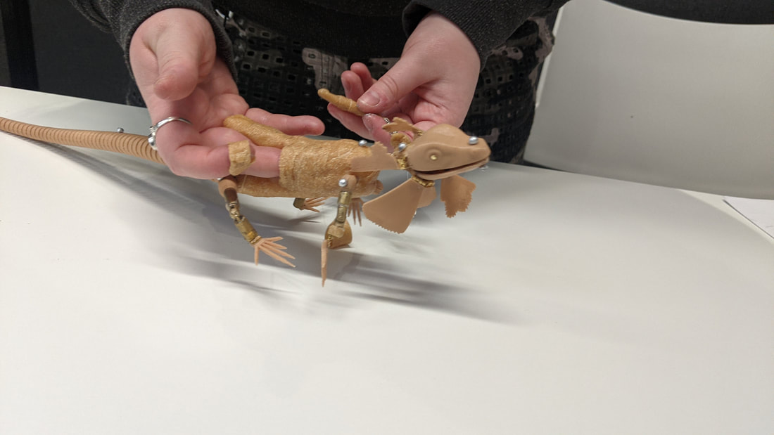
Below is some test footage: Left early leg test in new body, I struggled a lot with the feet being too floppy so i decided to make them sit more still but adding Worbla and glue around the hinge area. Right, frill test footage, unfortunately I was having issues with the mouth mechanism so it was not activated at the same time the frills open. Also, the activation was a bit enthusiastic resulting in too much movement forwards creating a 'pet cone' shape!
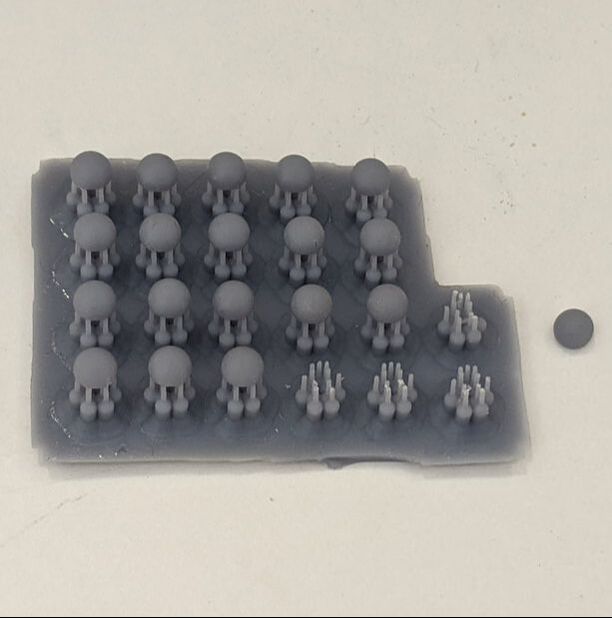
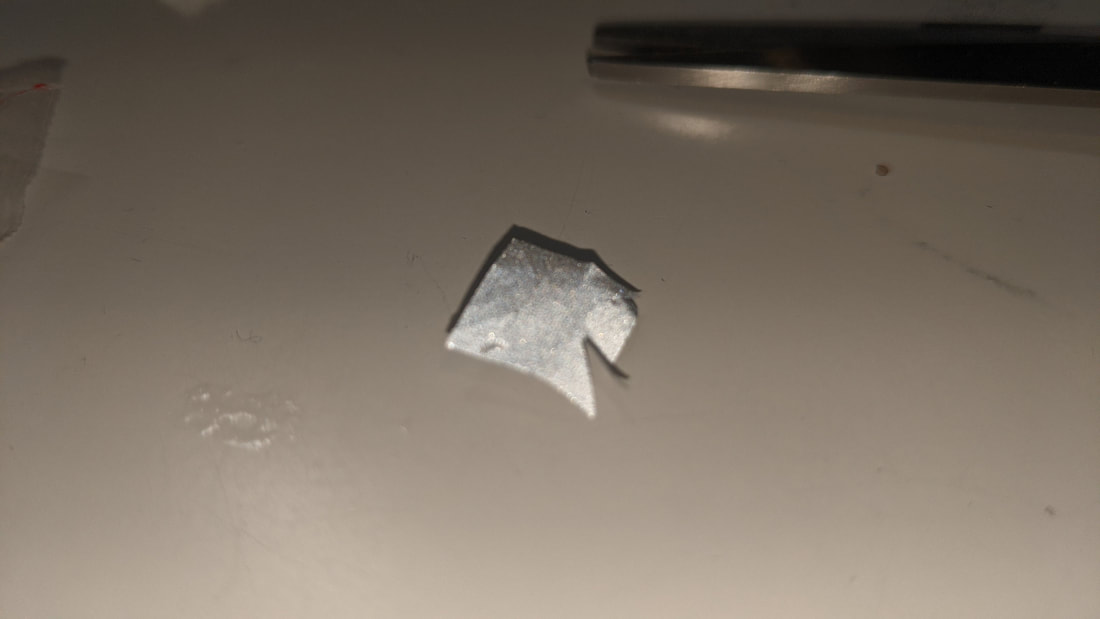
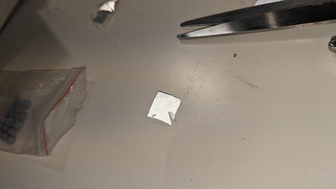
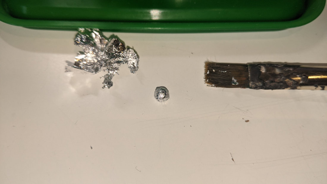
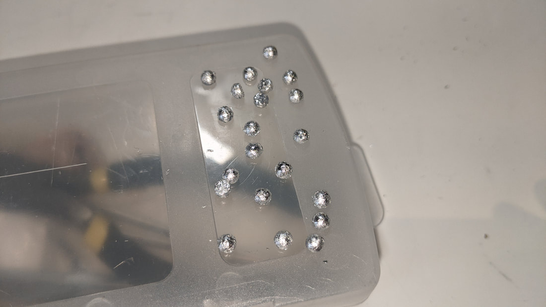
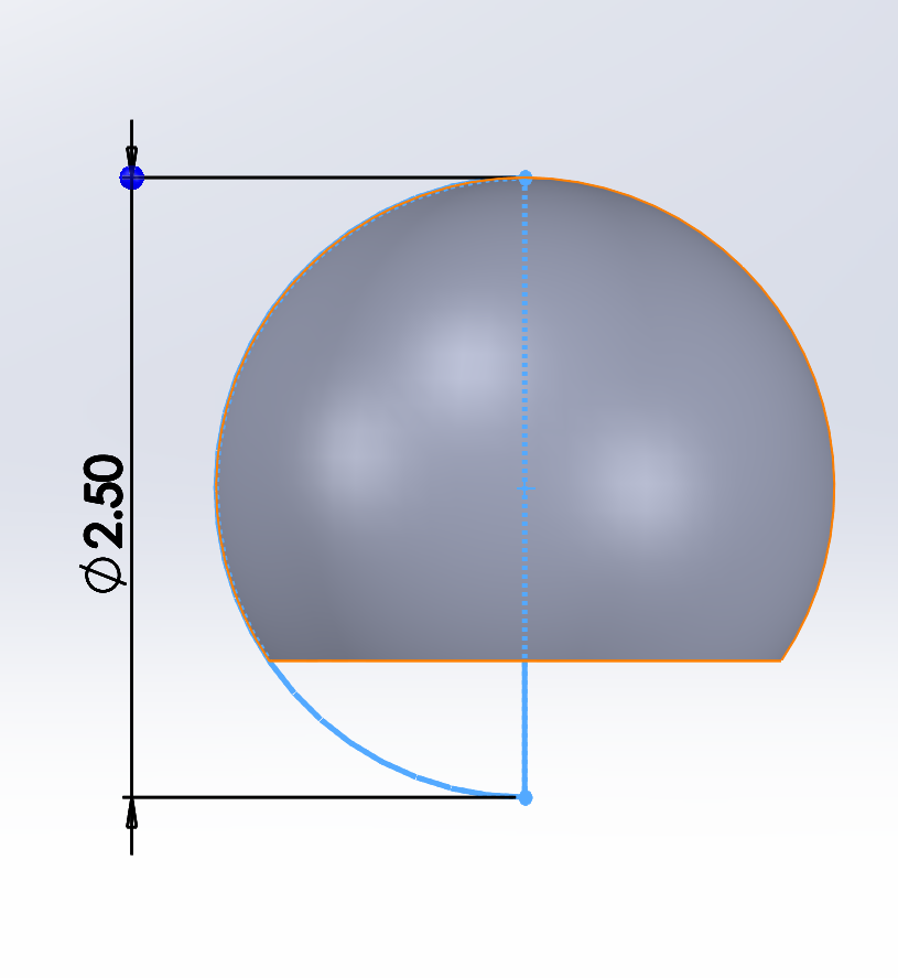
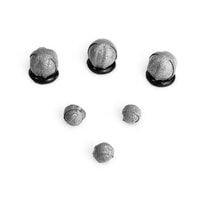
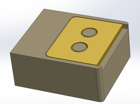
Motion Capture MarkersI attempted to use my reflective tape but the tiny size of these hemispheres meant that it wouldn't adhere. As an alternative I used silver gold leaf to get the shiny and contrasting effect as close as I could to the tape.
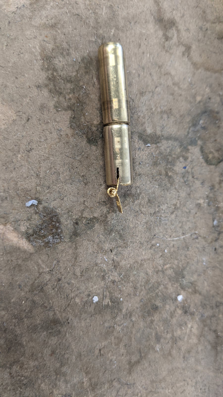
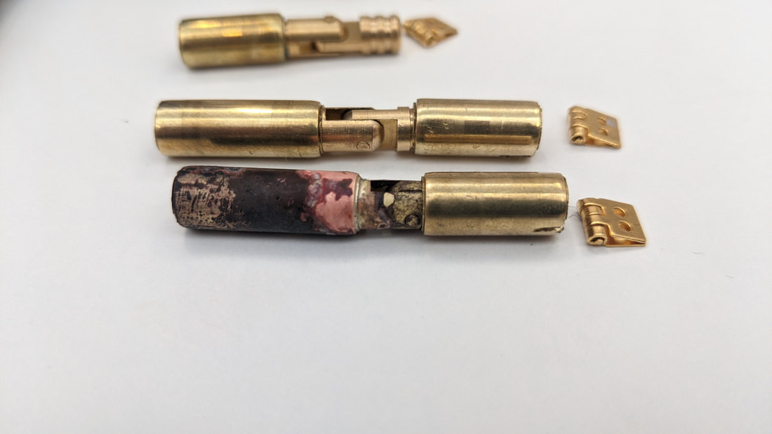
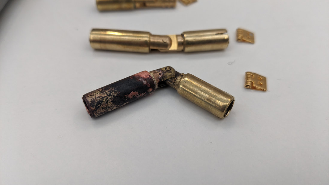
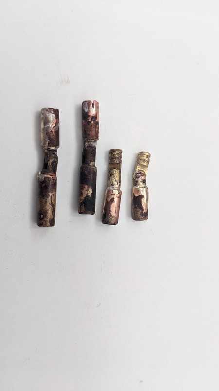
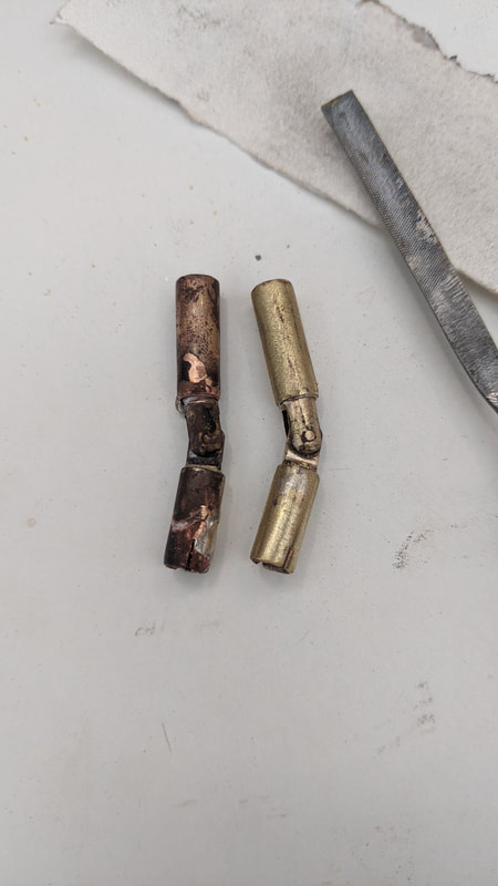
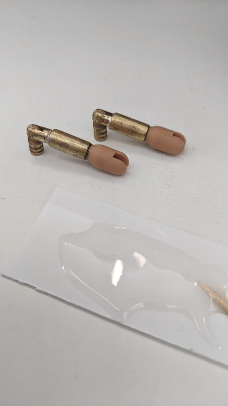
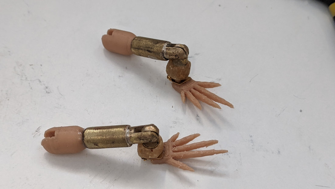
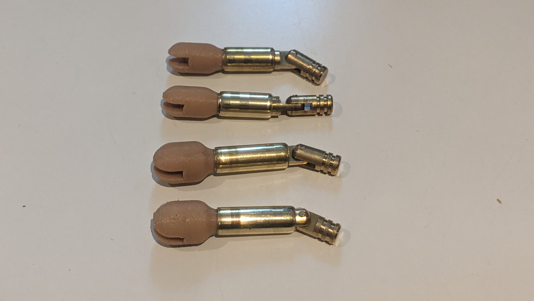
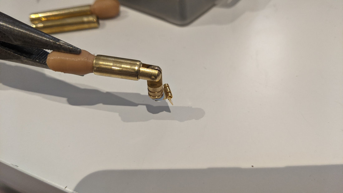
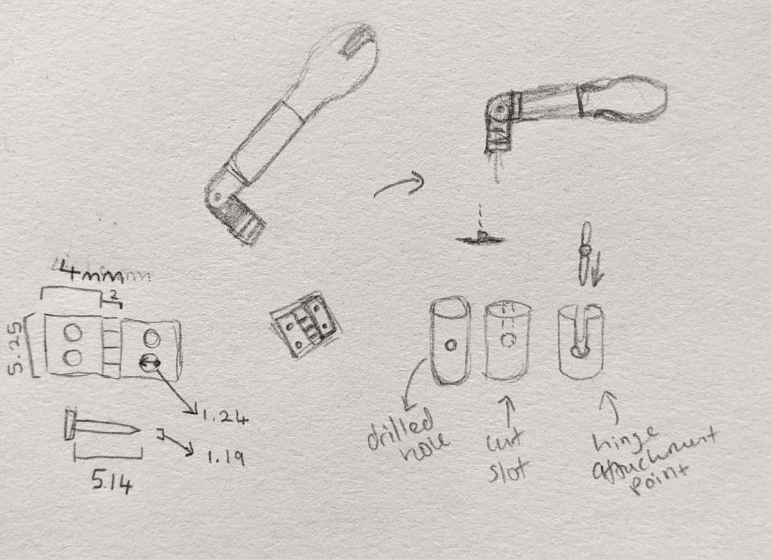
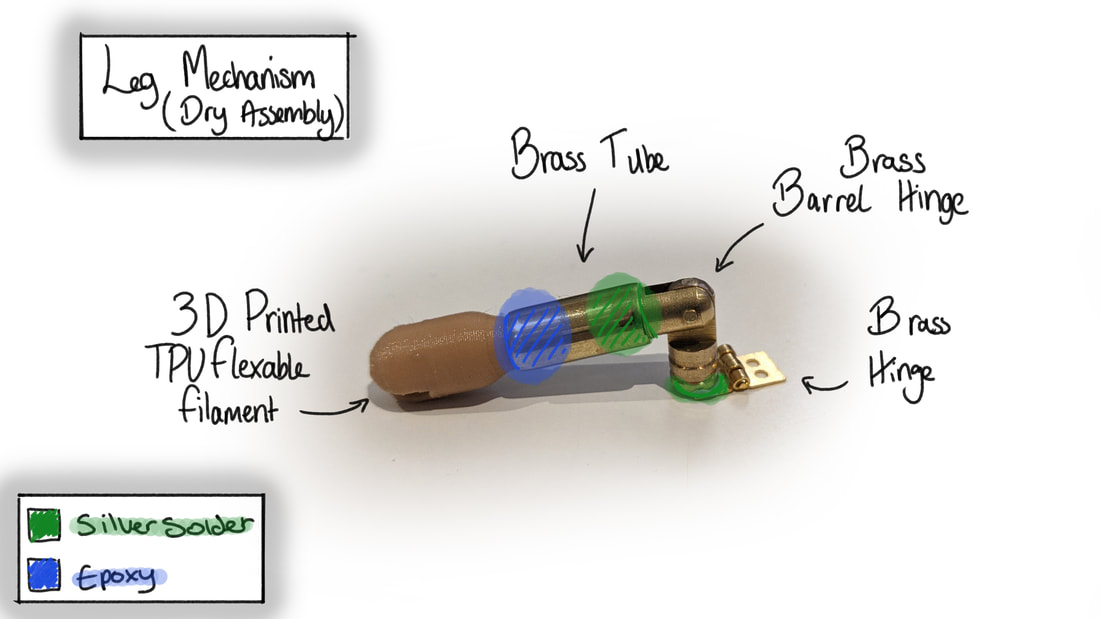
Starting the silver soldering process of the brass pieces: Image 1 - slot cut for small ankle. hinge to be soldered into the space Image 2 - a single freshly soldered joint on barrel hinge for knee hinge Image 3 - proof of movement, though the area will need cleaning after the second solder Cleaning, epoxy gluing and assembling the legs below. The last image depicts a slight change with the front leg design, I shortened the top section of the leg to compensate better for the size of the shoulder ball/joint. This change was relatively simple as it only required the two cuts and then a quick re-3D-print of the shoulder ball slightly shorter too. Also, unfortunately the small hinges I bought did not take the silver solder well so I had to opt for glue. A visual 'to do' list for my self (not pictured is the mock-up plastic body). 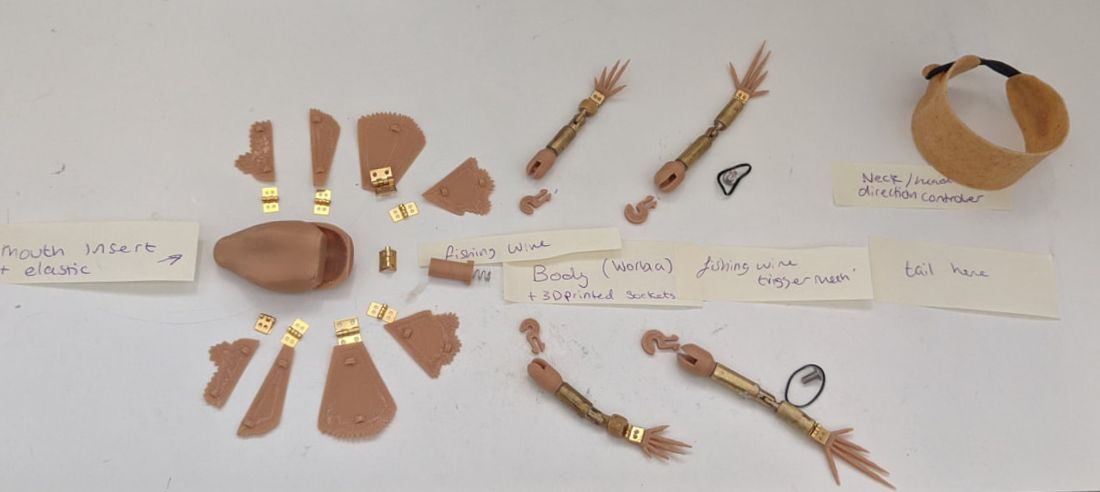 Feet and Legs
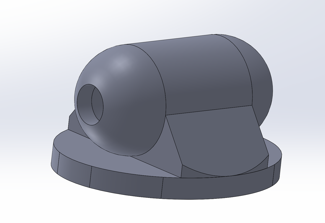
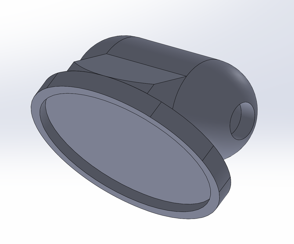
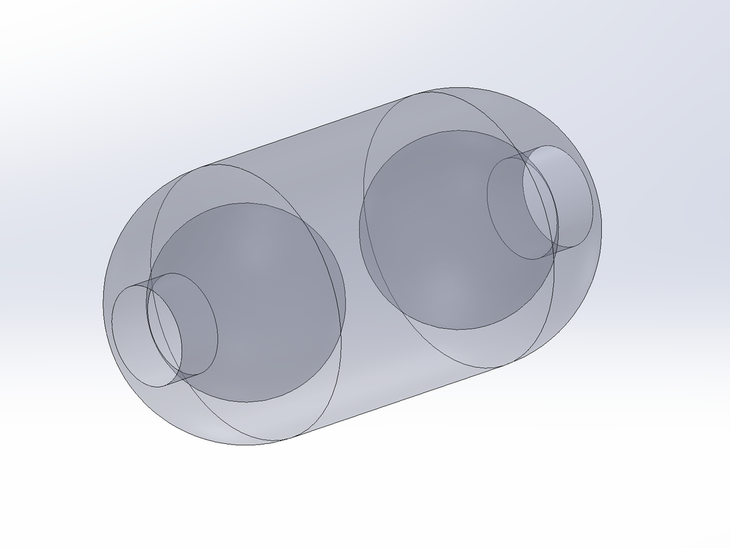
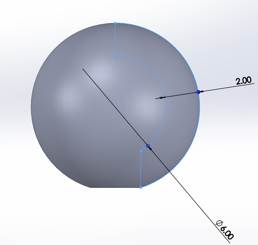
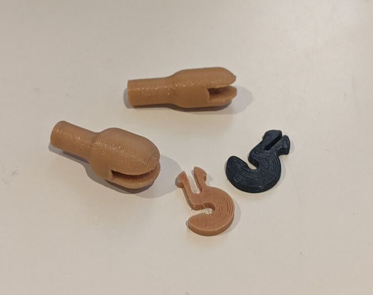
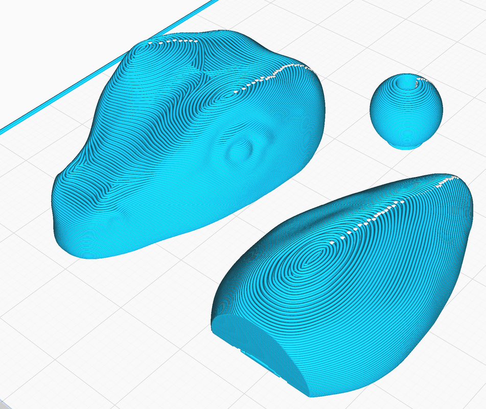
 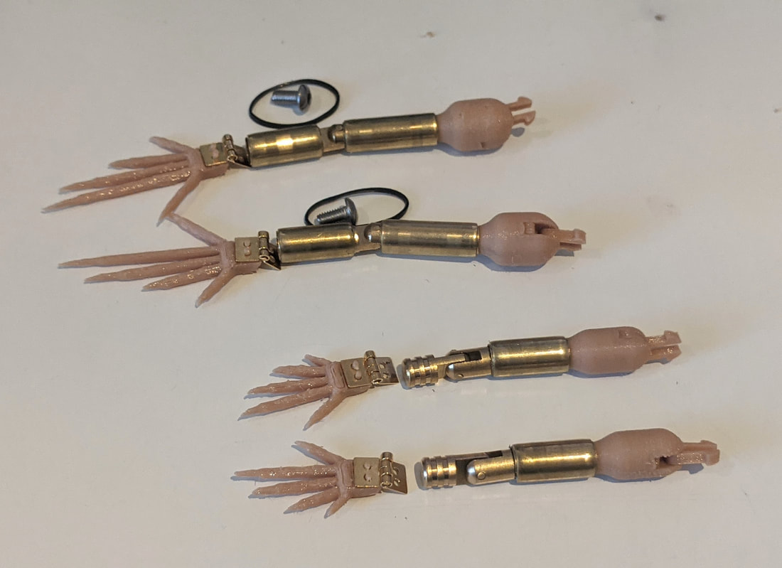 legs dry assembled I printed the hip cook hinges for the legs from the softer TPU as if super glue is added to them they become more firm and the layer lines do not separate as they normally do. I much prefer this to using the firmer black TPU filament. Shoulder and Hip SocketsInitial test design of the socket for the hip and shoulder joint:
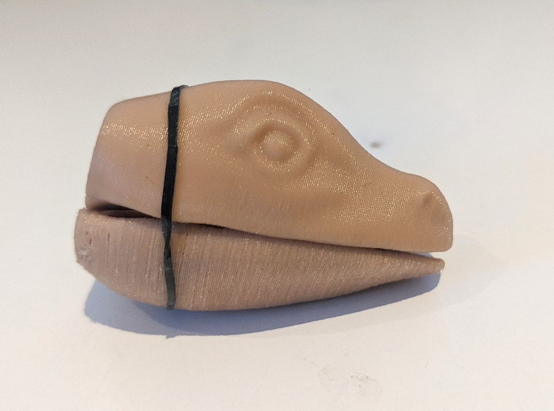
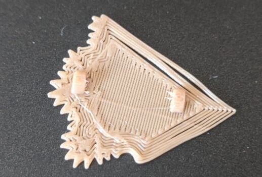
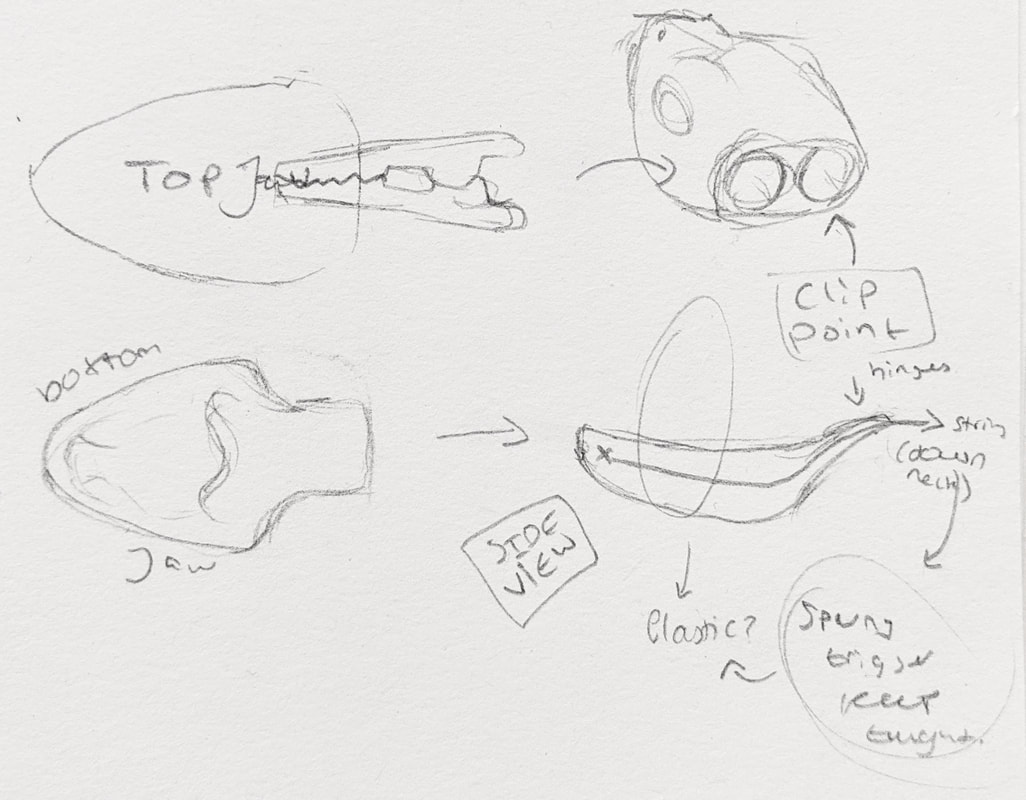
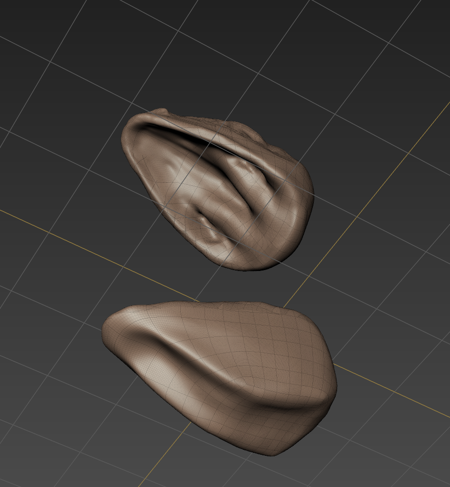
Head Redesign for PrintingThe top jaw printed ok but the lower jaw failed. Also, the two don't fit together well as shown below (a band holds them together temporarily):
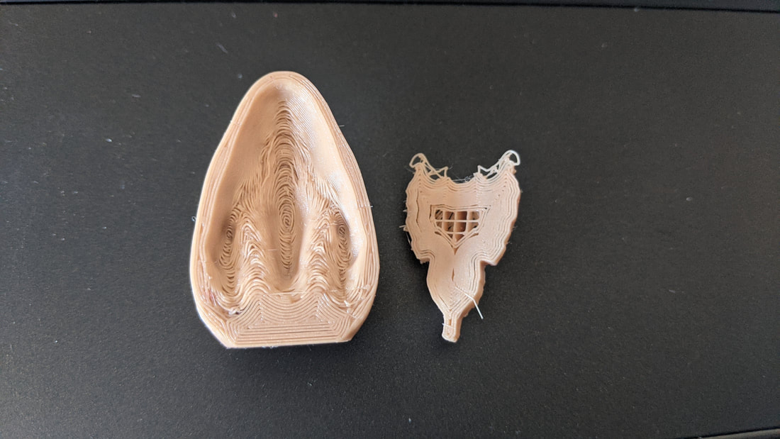
 Re-print layout and socket Unfortunately this Cura layout wasn't successful as it created a messy surface finish.
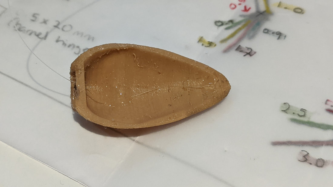
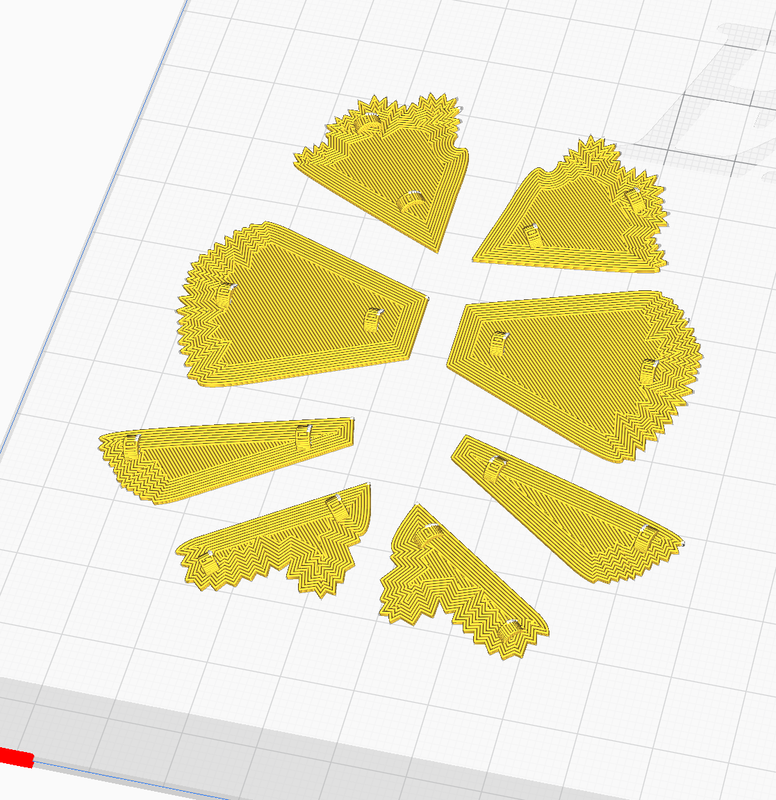
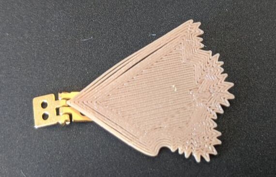
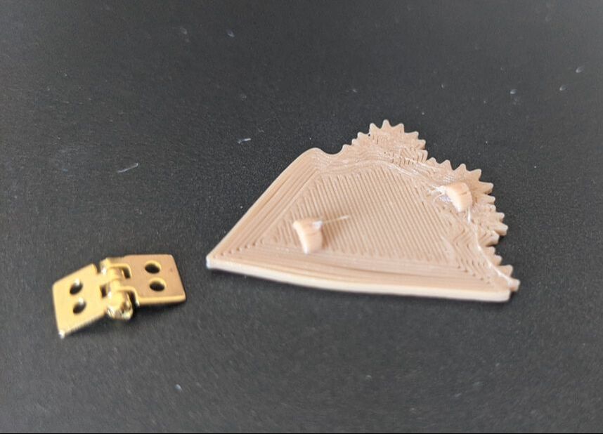
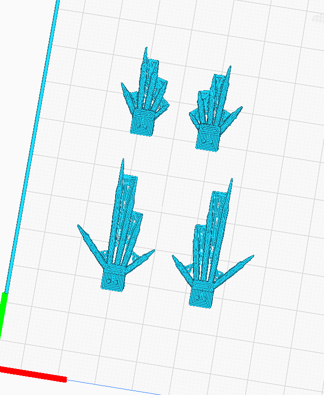
 Head Frill
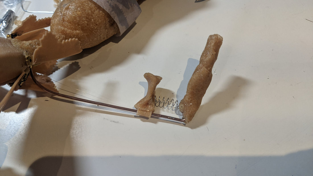
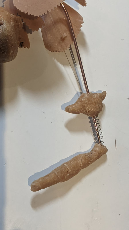
Head Mechanism Spare TestThese tests are made from older prints: - hinge glued in place which I want to CAD like the ankles to have two pins which are then epoxy glued in place for a strong hold. - integrate the fishing wire into the jaw with CADed holes/channels for it to run through. - integrate the elastic inside the upper and lower jaw by having a separately printed inside parts that can sit in the hollow head shells. - CAD the hole for the neck control stick.
After this test I have been considering going with a two handed design to improve head control rather than relying on one hand and my wrist to do all of that work. Neck
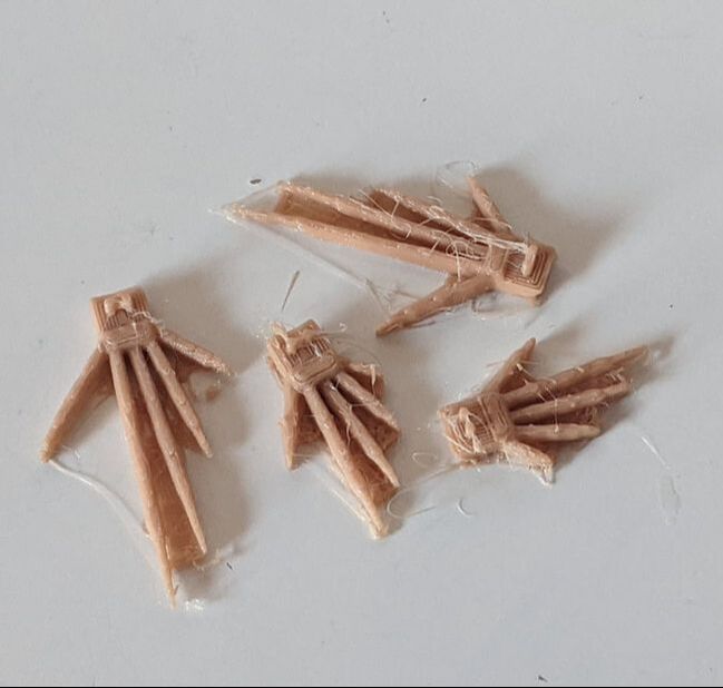
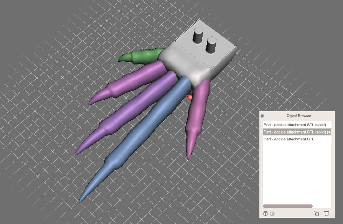
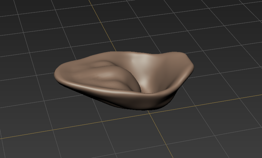
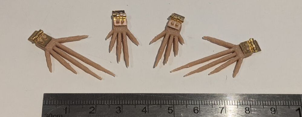
Lizard Feet: Solidworks to Autodesk Meshmixer and then Cura for PrintingAs solid works lends it's self to hard edge designing I brought the ankle/hinge attachment into Meshmixer to integrated more organic shaped toes into the model. I used the measurements from earlier in my model designing to get all the toes the right length and used the same file to do front and back feet. When this was done I duplicated them and mirrored them in Cura. I also softened the area of the Solidworks model in Meshmixer using their sculpting tools to ease the transition between the parts. As I am not aiming for realism but representation of the lizard I think this will work well once printed in the flesh coloured flexible TPU filament: my concern with the model is its tiny proportions and the separation of layer lines that can happen with this filament. To fix this hopefully some superglue once the supports are removed. For this small of a model I would normally opt for a resin print but as I need it to be flexible and matching the other areas of the model.
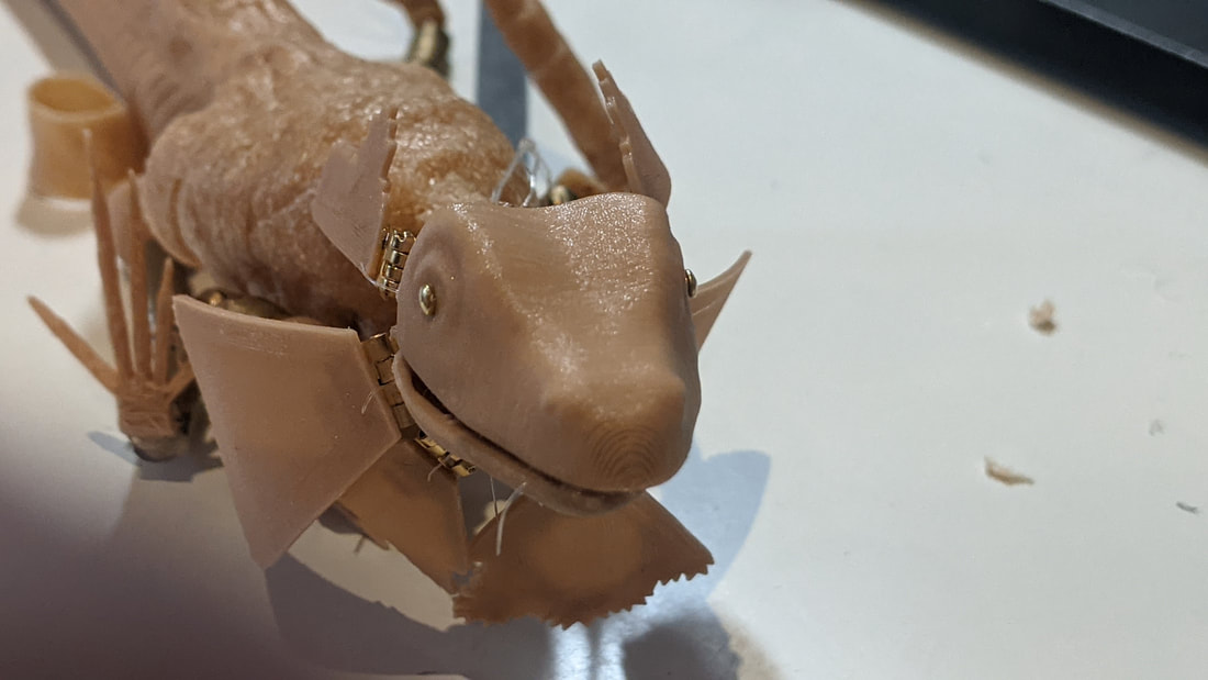
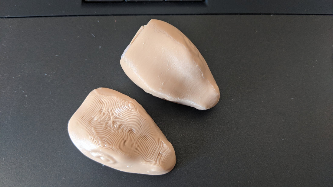
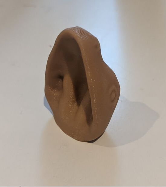
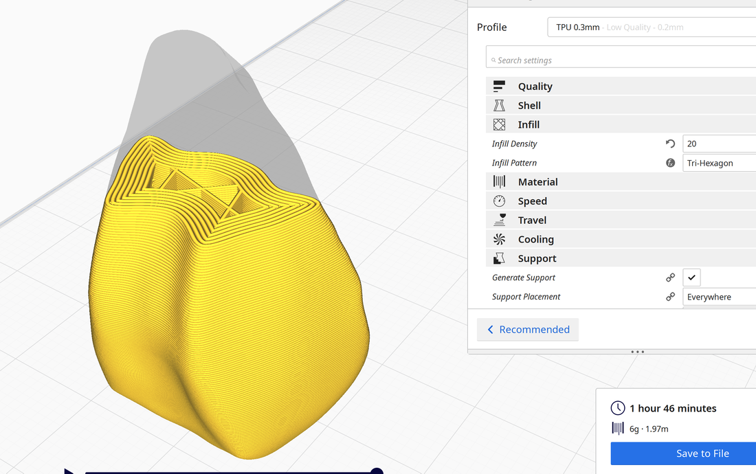
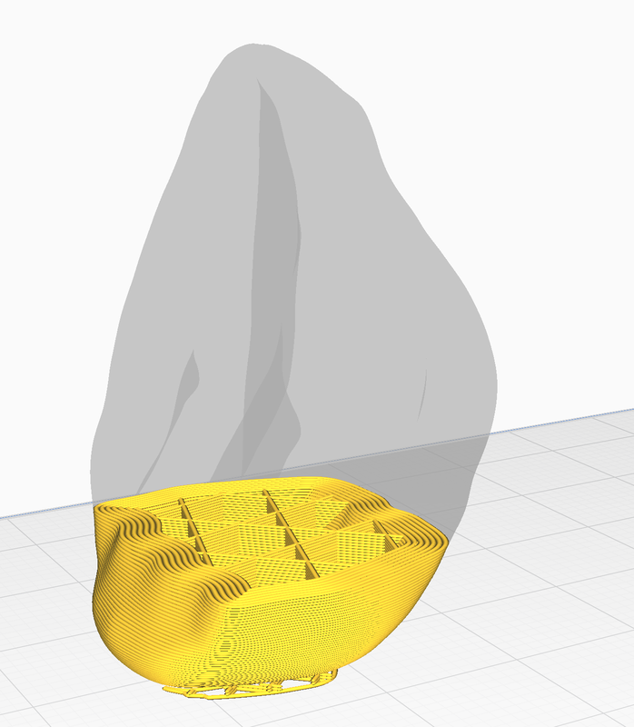
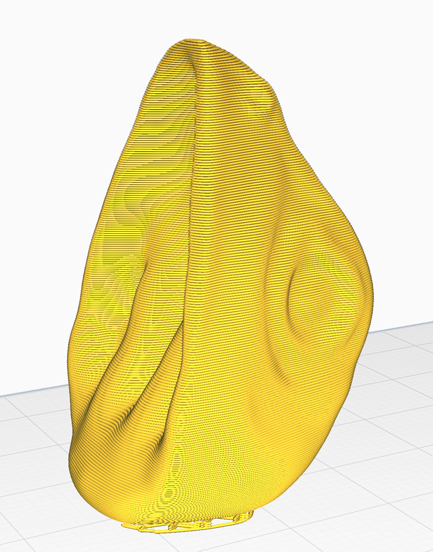
Lizard Head Update
Feet
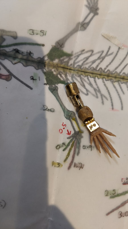
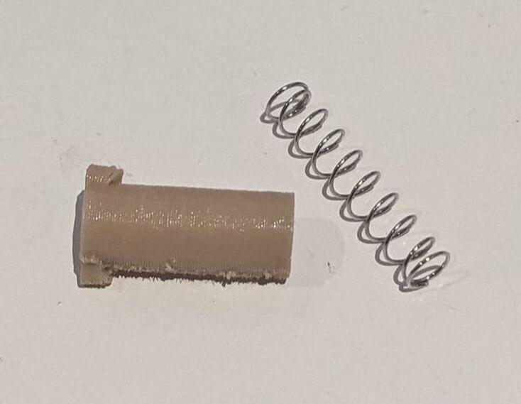
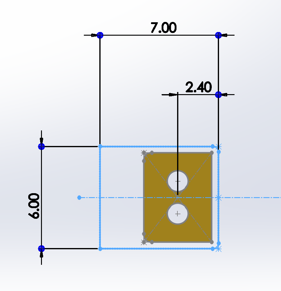
It will be a very small print with the cube modelled here standing at 3mm tall - Lizard feet are not big. Their front feet are slightly smaller than the back so a smaller iteration of this will need to be made. After discussing the design with my tutor he suggested that making the 3D printed pegs that fit in the hinge holes taller so they can be melted flat on top of the hinge, holding it in place.
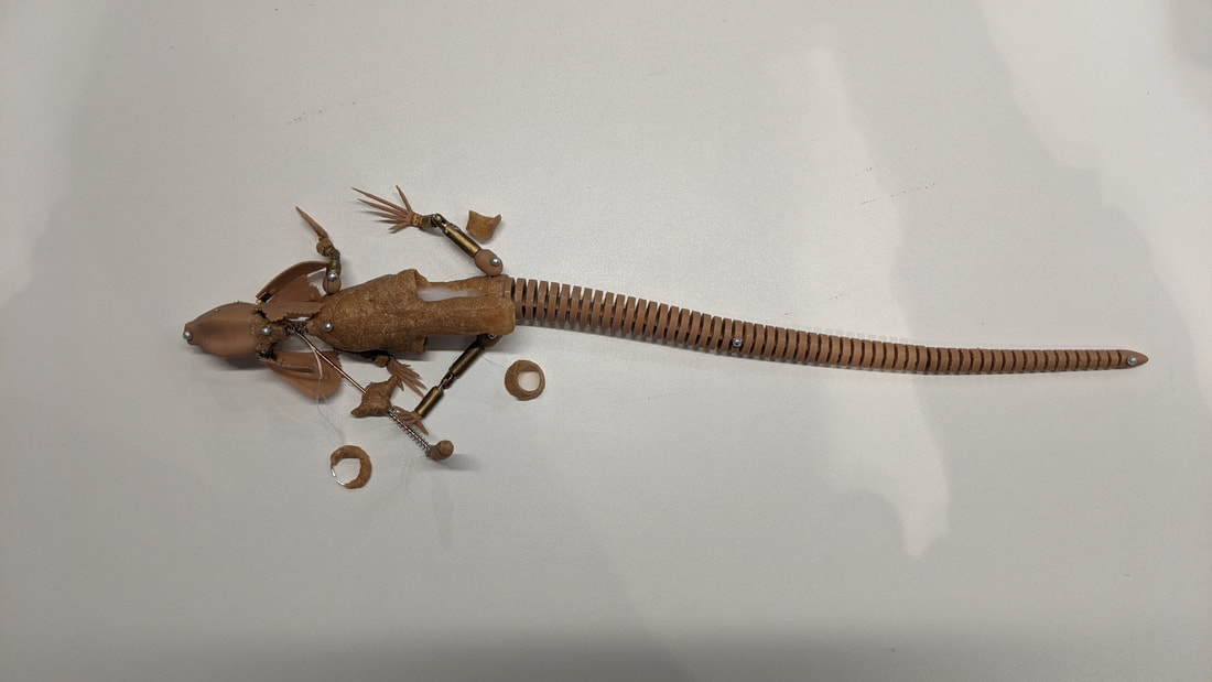
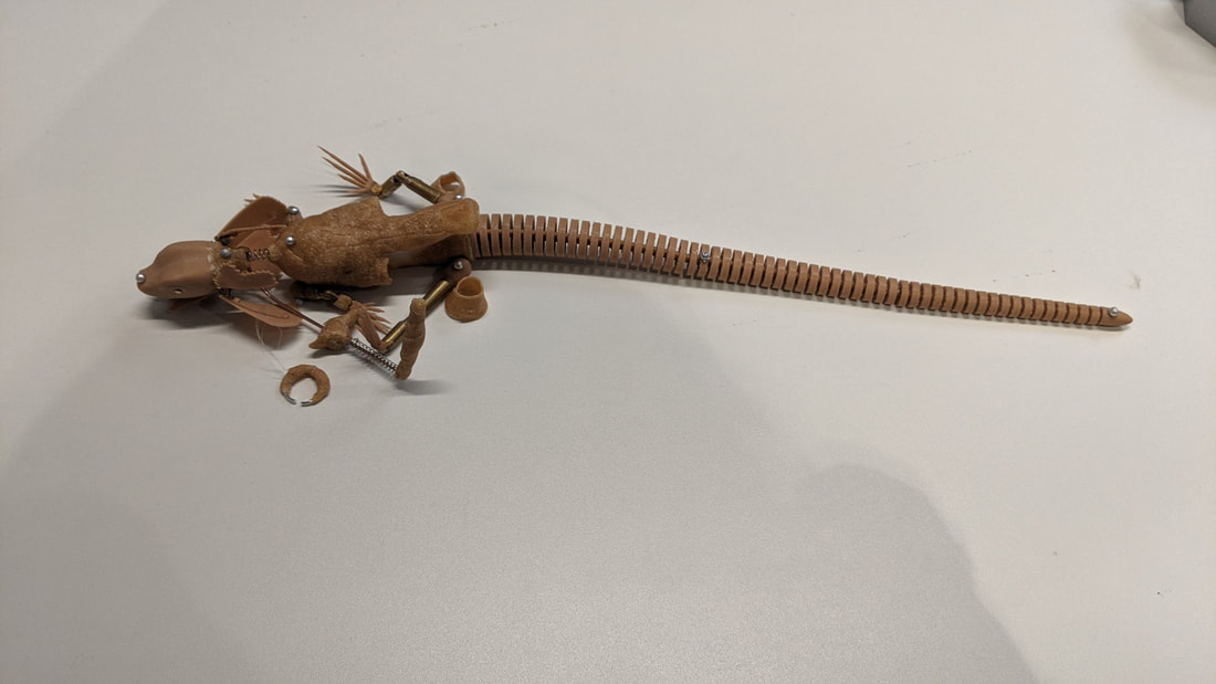
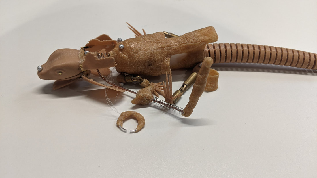
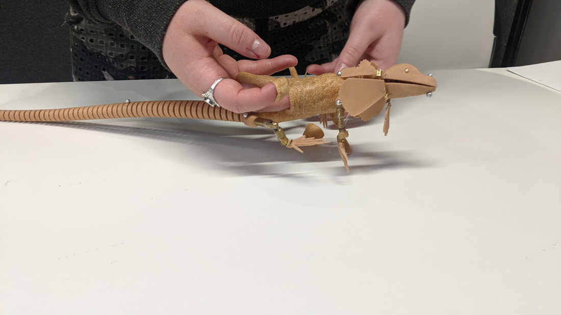
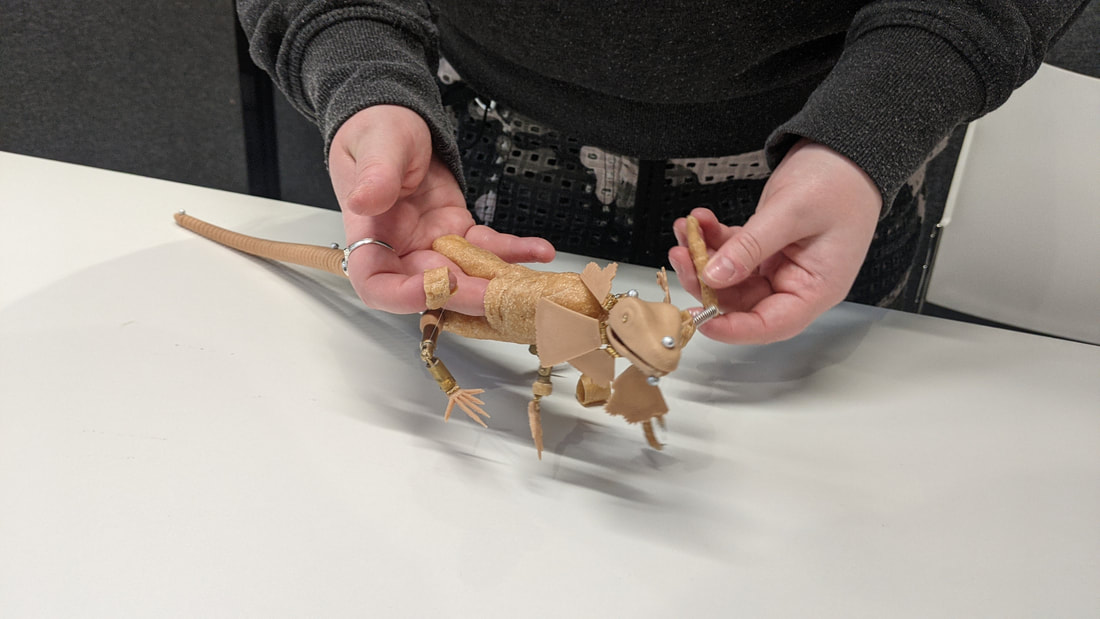
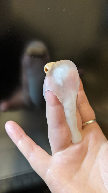
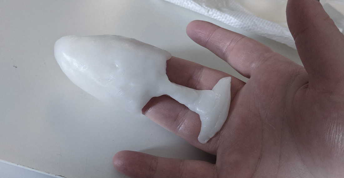
Puppet So Far...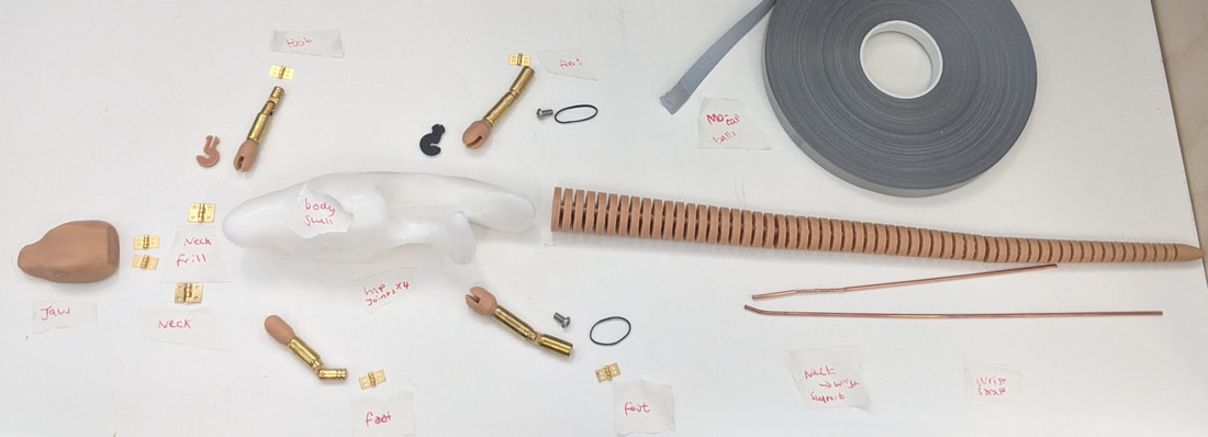 Body: I planned on making the shell for the body entirely 3D printed but I want to experiment with the thermoplastic Worbla (in the same brown tones). The white thermoplastic pictured here is a polymorph plastic moulded to my hand in the correct position for puppeteering - I want to use this in the areas that need very close fitting to my exact finger shape on the inside of the lizard body. This is a great material for this purpose as it can be heated up with hot water and reformed when experimenting with shapes. More images below of how that fits to my hand: (The part at the top of my fingers would be the lizards ribcage area, the tail would come from under my hand etc.)
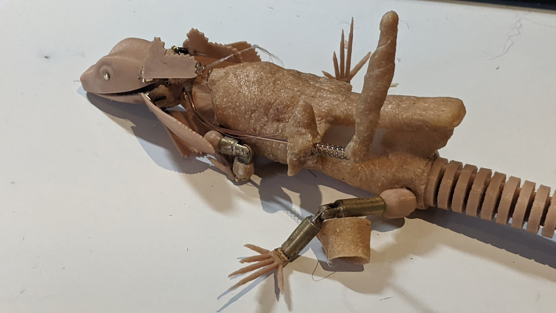
Tail: The tail is finished completely apart from needing to be attached to the body.
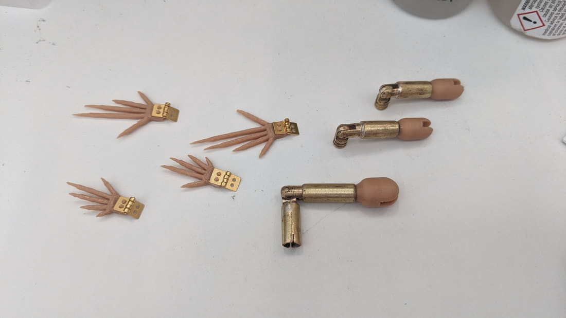
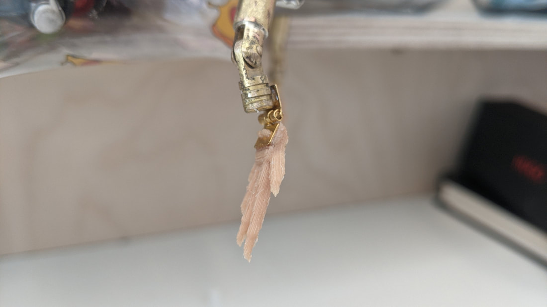
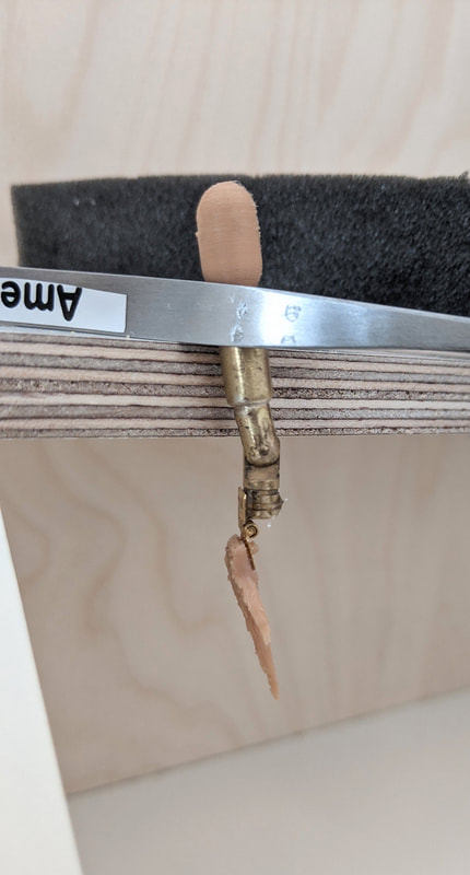
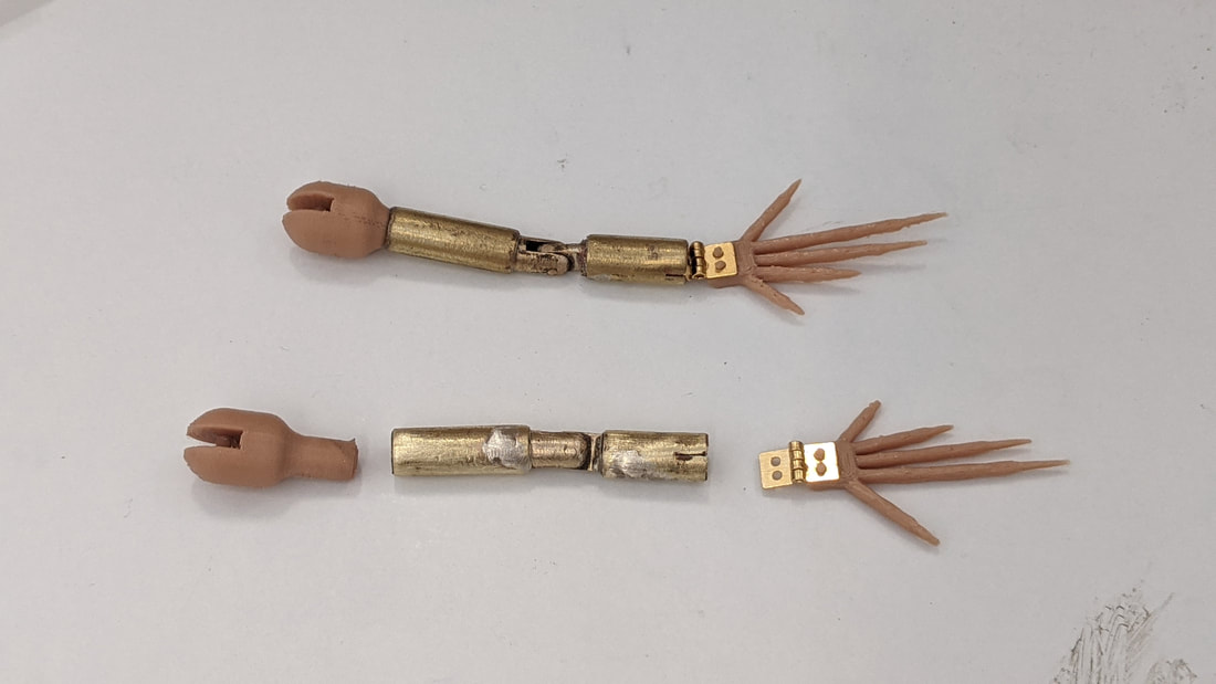
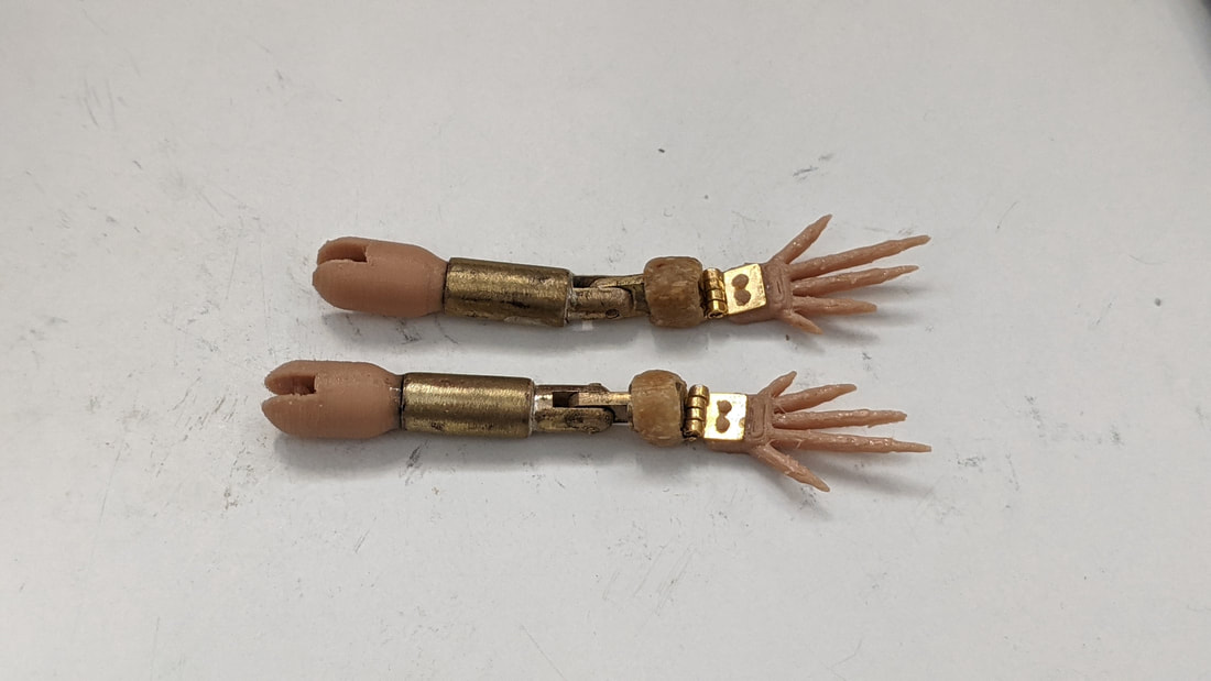
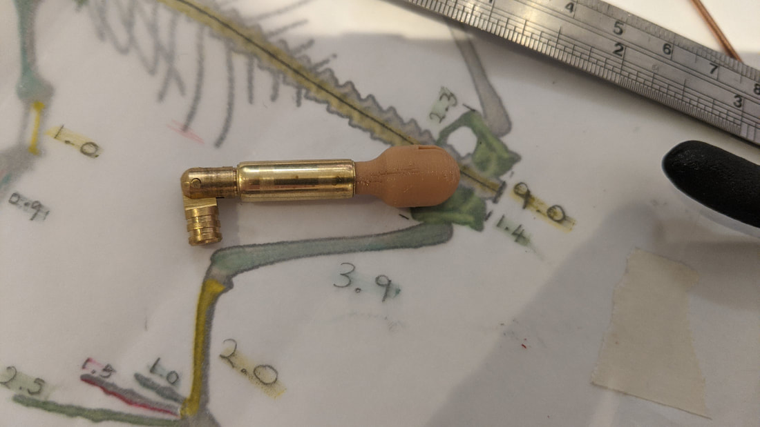
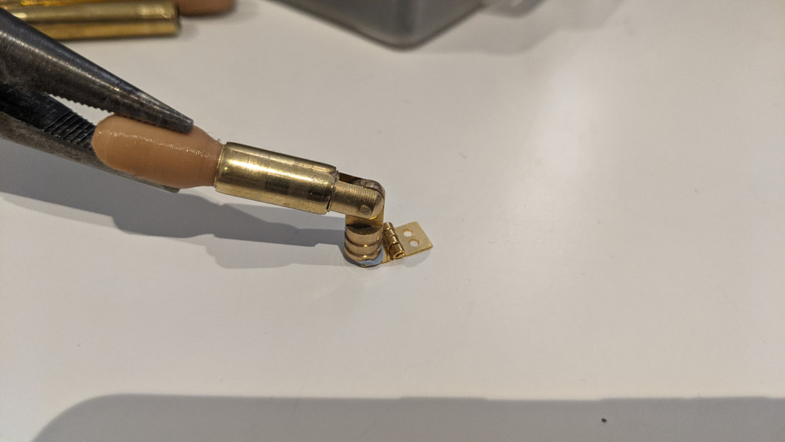
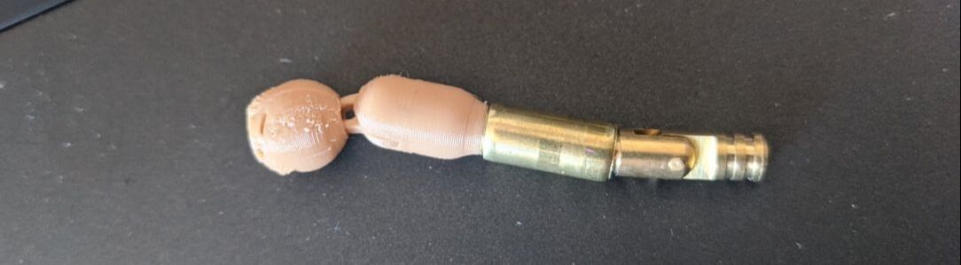
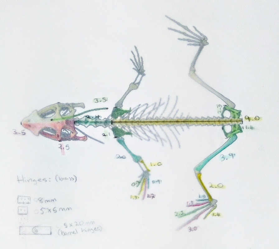
Legs: The feet are in the process of CAD designing and will need to be printed in the brown flexible TPU filament. The legs also need their hip and shoulder hinged simply printed in the black TPU filament. The finger attachments on the back legs are going to be made with small back elastics attached with M3 screws into tapped holes in the brass leg pipe. Finally, assembly needed. Head: Lower jaw needs a new digital model more simple than my last design so the hinges pictured can be simply attached and wire can be run through into pull it open. This area will be heavily connected to the neck frill and mechanism here. Neck: The neck will be made from a spring and the space inside will be used to run the wire for the frill mechanism. I want to coat it in the Worbla to match the body hopefully if it will move. If not a simple 3D printed flexible tube will cover the spring. Wrist Mechanism: Here will be how the head is supported - pictured above are some welding rods i can use to cover the distance between my wrist to the head. Not pictured is the small crocodile clip I have to clip into the back of the puppet head for easy removability. Also, the soft material need to attach it to my wrist - perhaps 3D printed but most likely Worbla can be used as it is popular in the Cosplay community for moulding parts to be warn such as this. Motion Capture Markers: Reflective tape pictured above is perfect for attaching to small printed balls that will be placed advantageously over the completed puppet. Plan of Action For the Last Two Weeks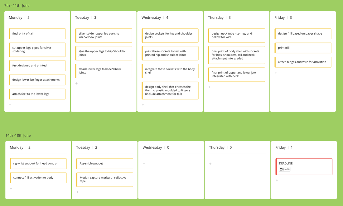 Shoulder and Hip Joints
Leg Development
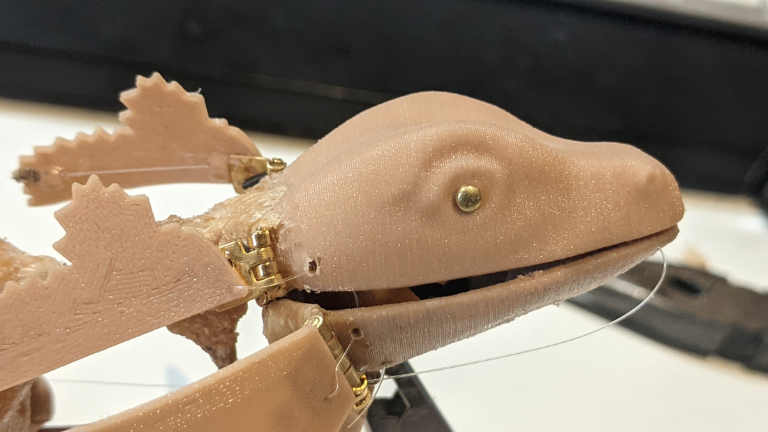
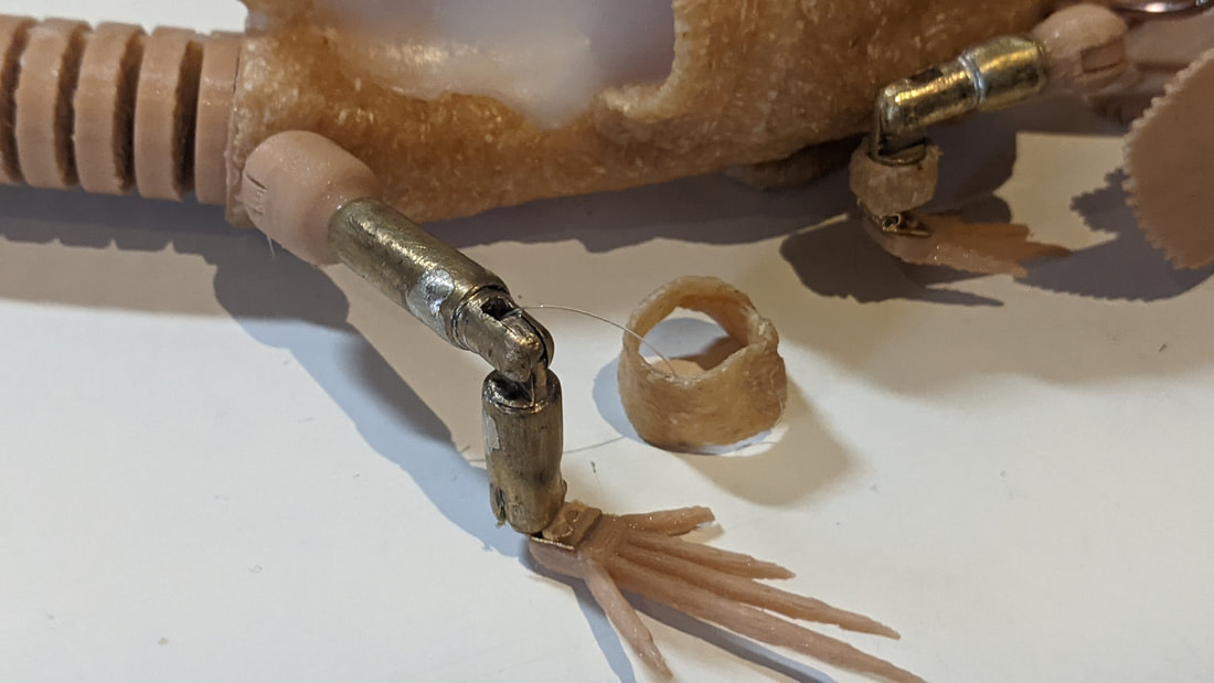
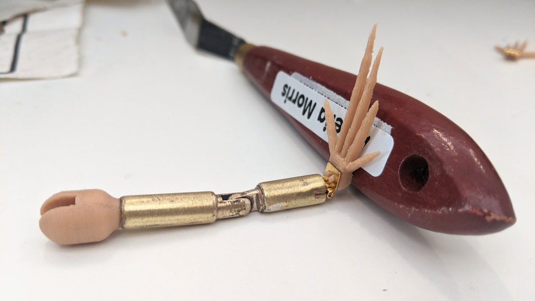
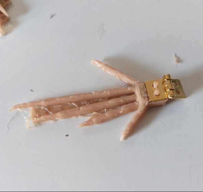
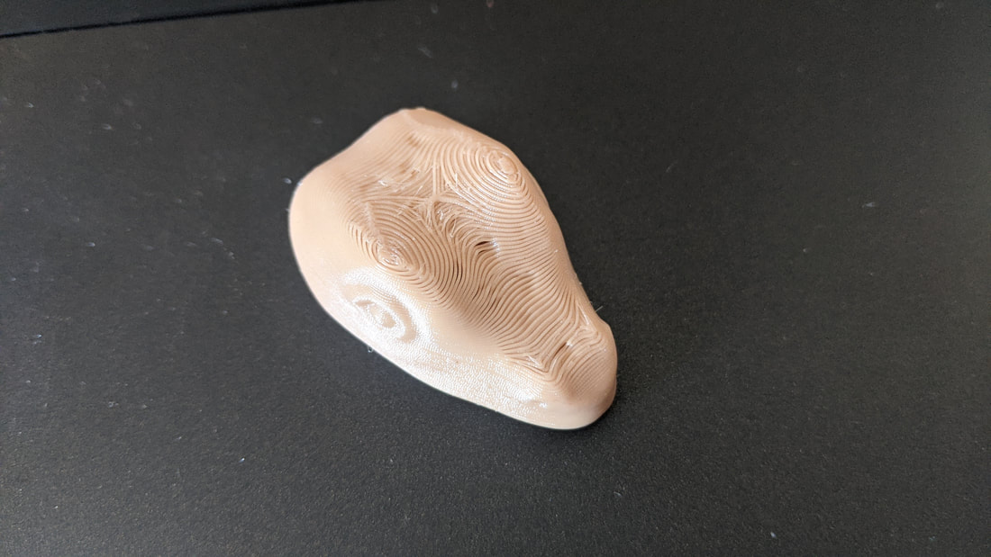
Also on the back legs are the points where my little and index finger control the puppets two back legs - this will be from the segment mentioned above of brass tubing between knee and ankle hinges. I am currently playing with ideas of using something less rigid than wire as it needs to allow for a lot of multi-directional movement and still be comfortable on the fingers. New Printed Head ModelI am much happier with this shape - the next steps for it will be adding the clip mechanism for the wrist attachment, the connection to the neck, the lower jaw and frill mechanism.
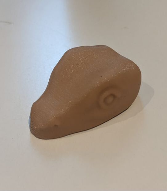
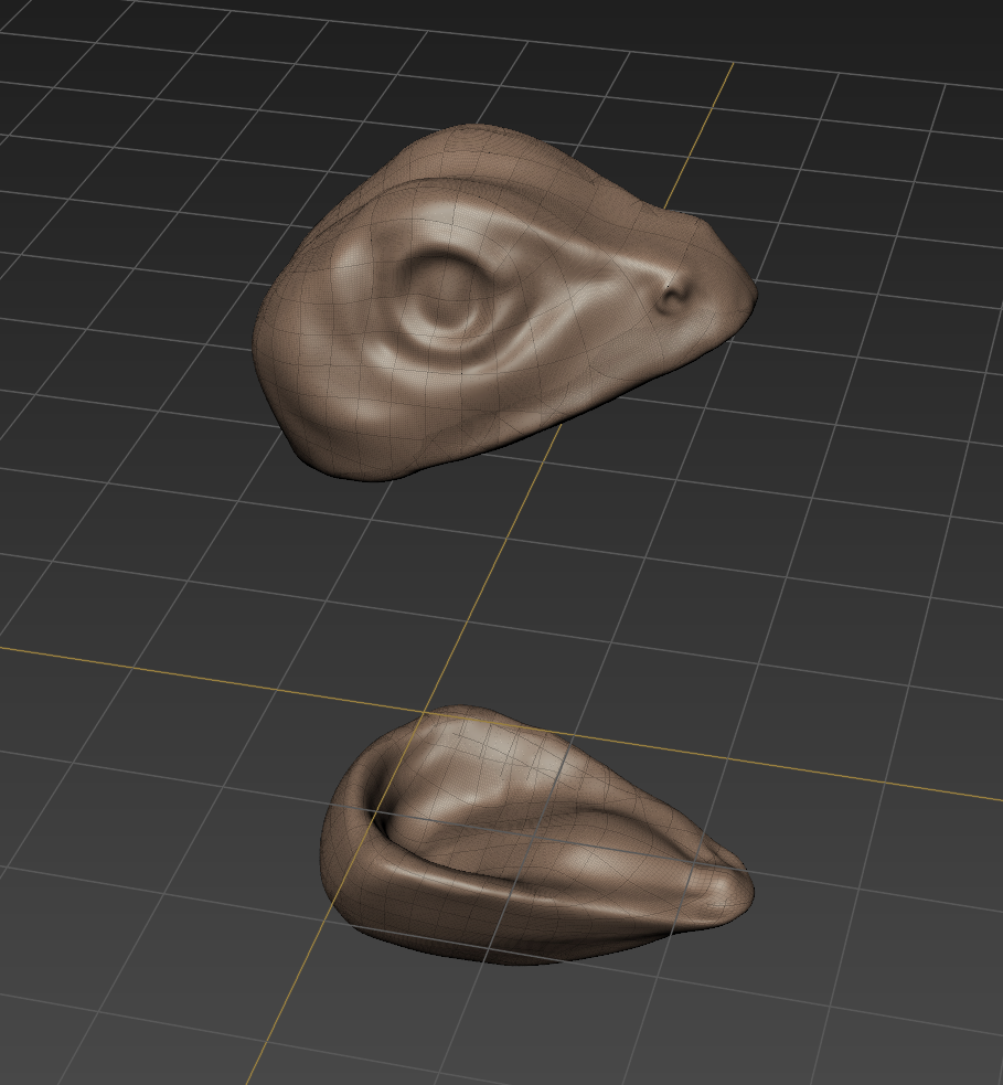
Head Design: Mudbox Modeling
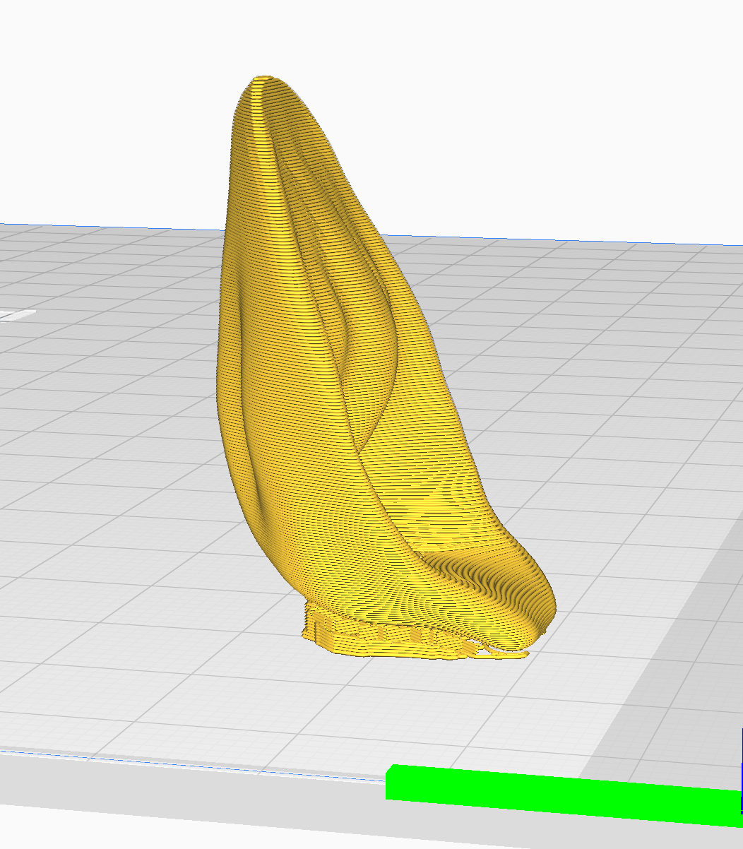
Model in Cura
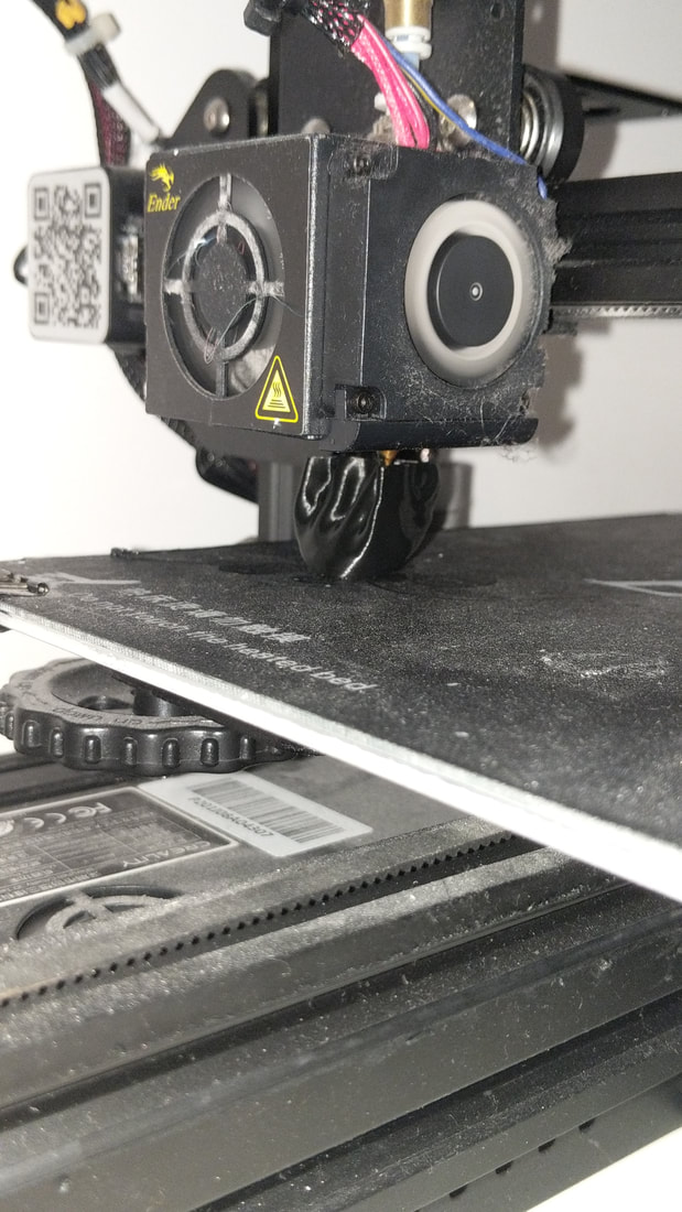
3D printing in the TPU filament in black for test print
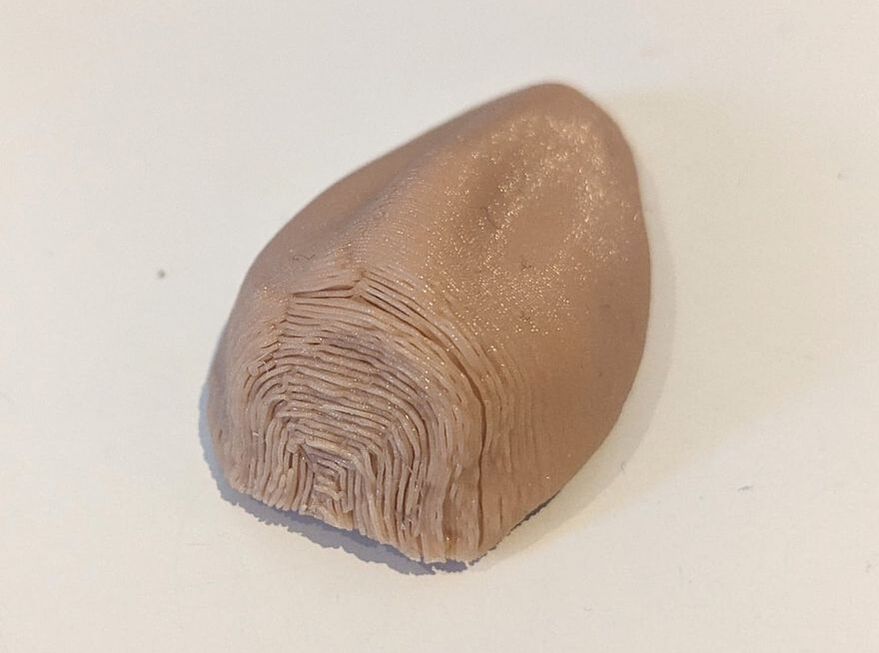
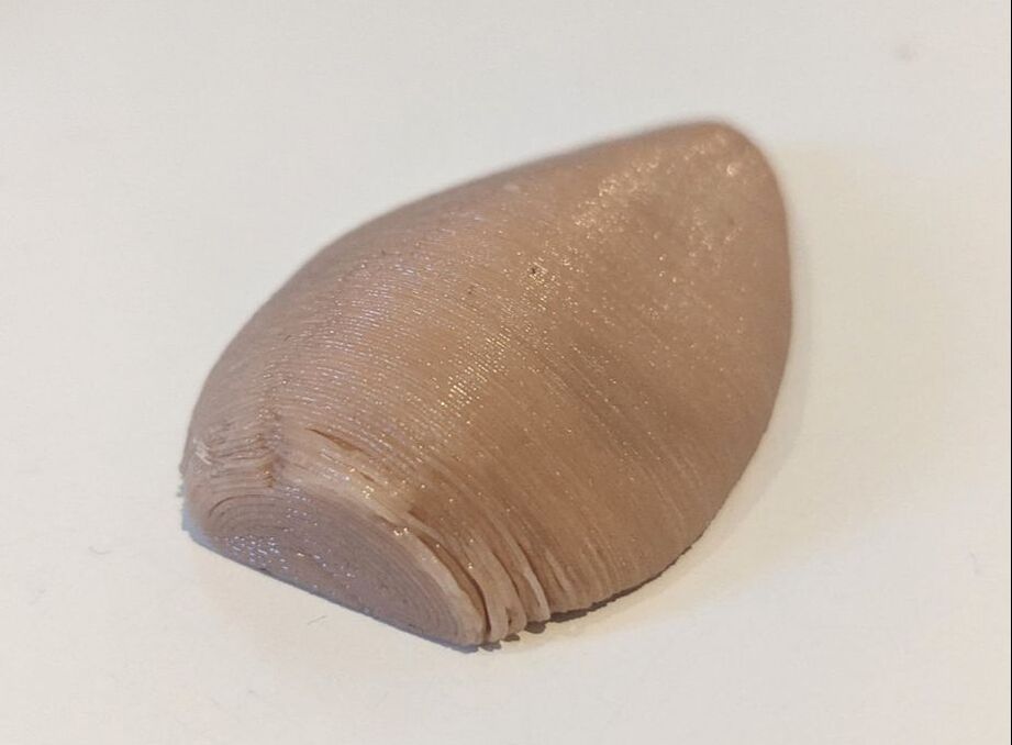
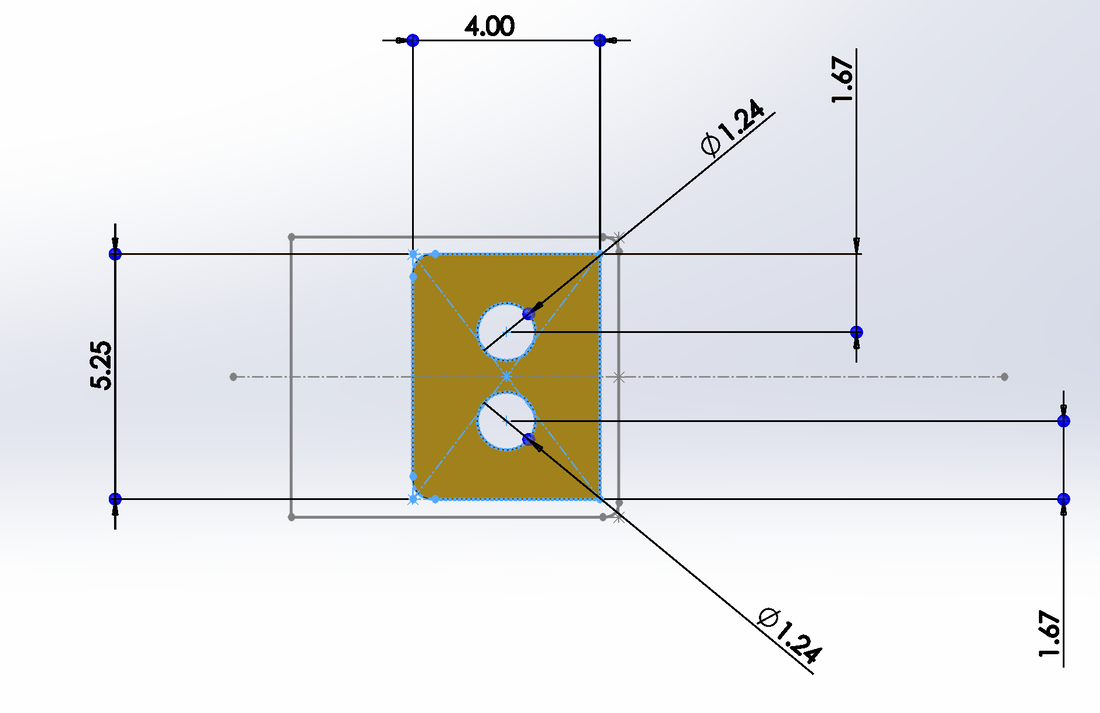
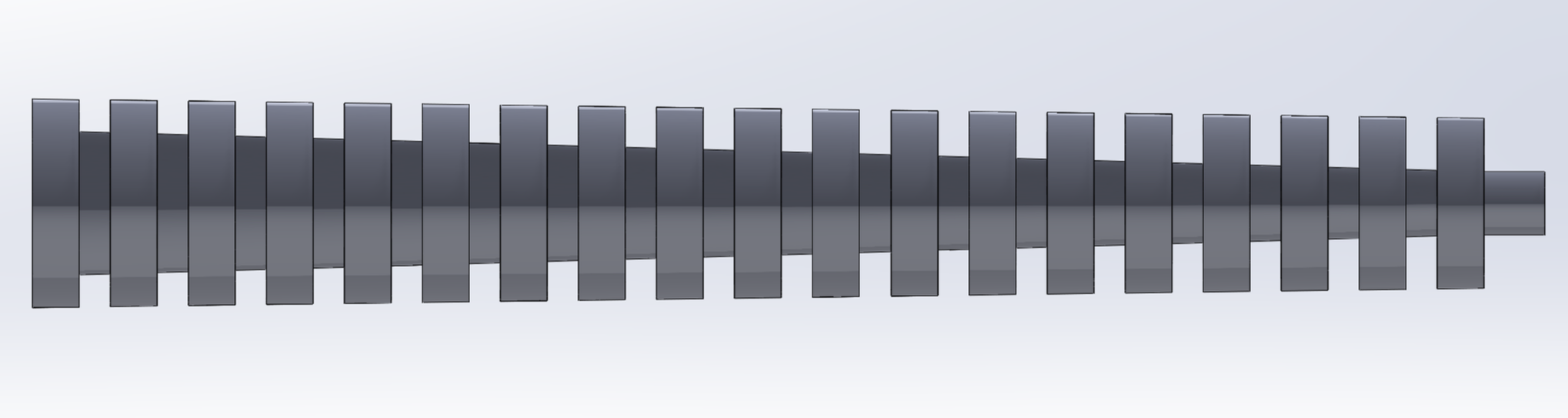
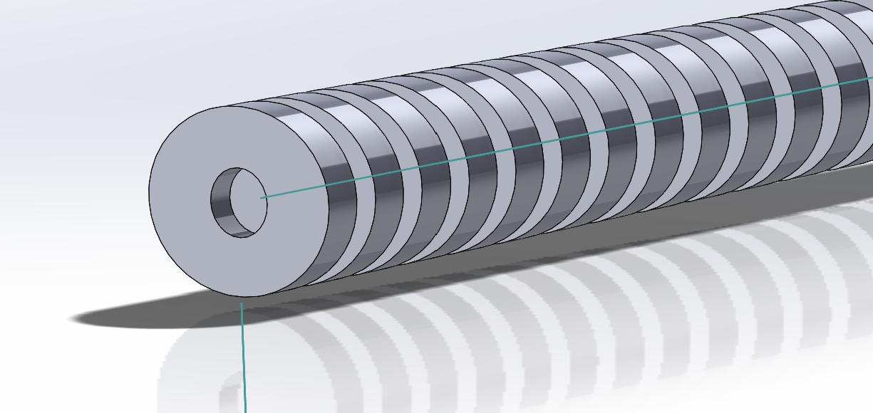
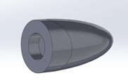
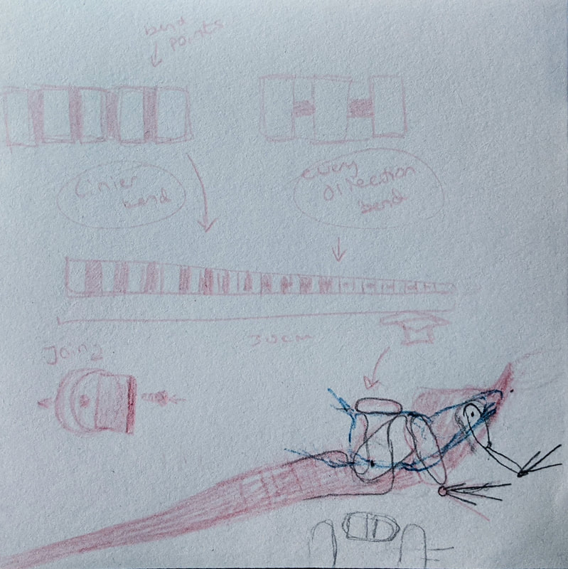
RedesignRedesigning the head to be a more realistic shape: 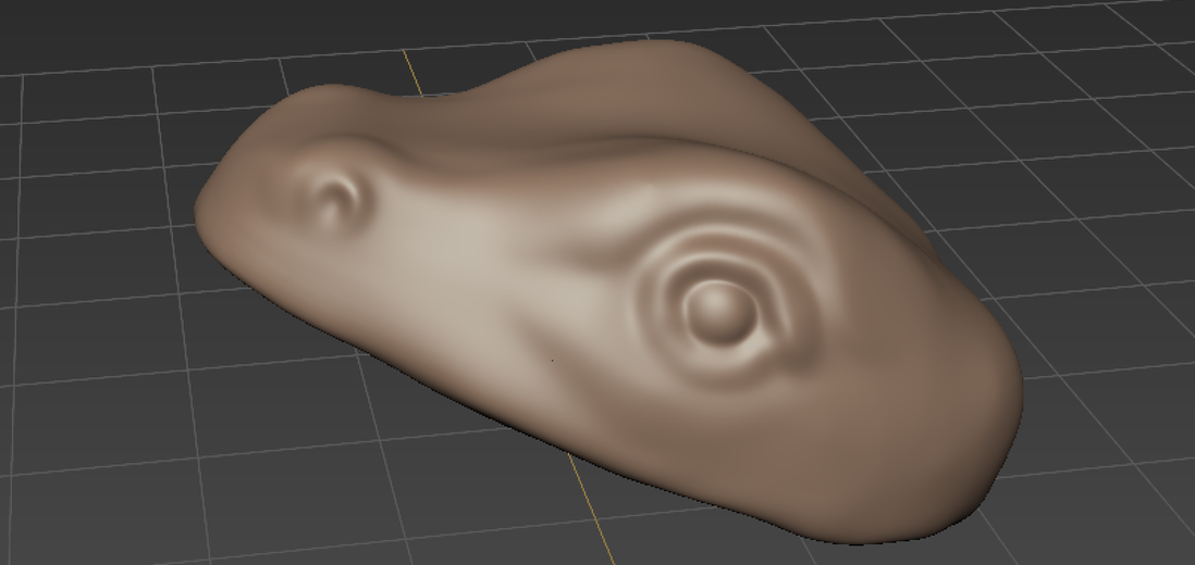 Hip Joint DesignsTo replicate the movement needed for the legs i designed this hip joint. The first design was too stiff for the free movement needed so I altered the one pictured below (a smaller shoulder joint) and designed the two new joints. Technical drawings below depict the new designs. 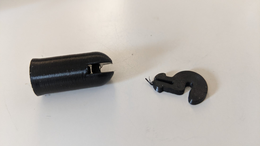 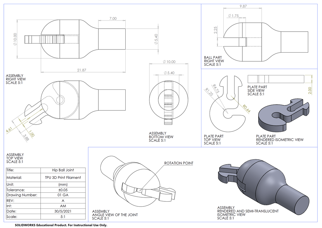 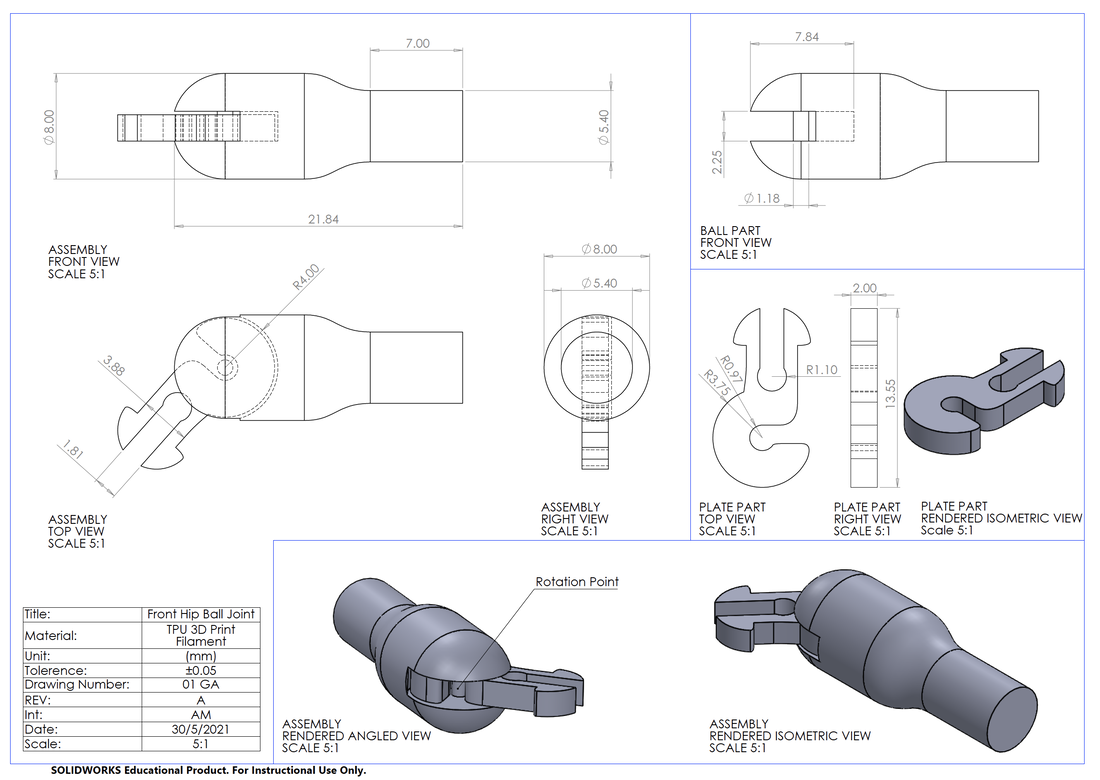 Digital Model of Tail Development - Design 2Here is a revised tail design; the model has been divided into smaller sections. It also has been altered on the first half to make the movement mostly in only two directions to increase the control over its flexibility. 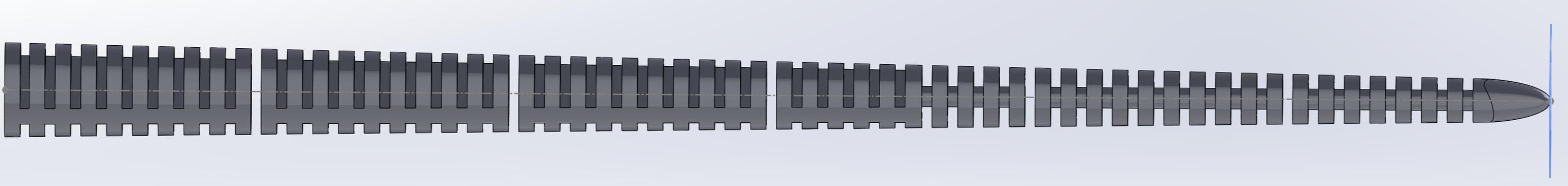
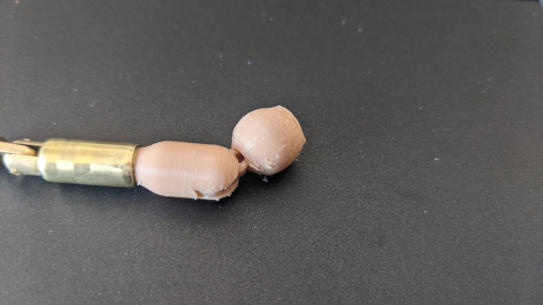
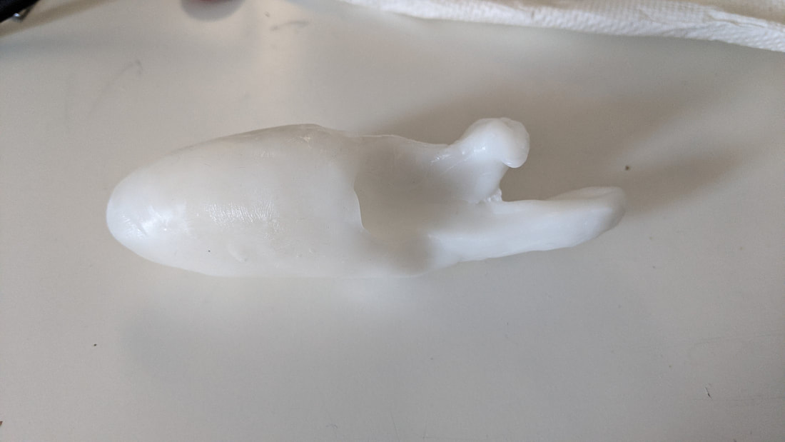
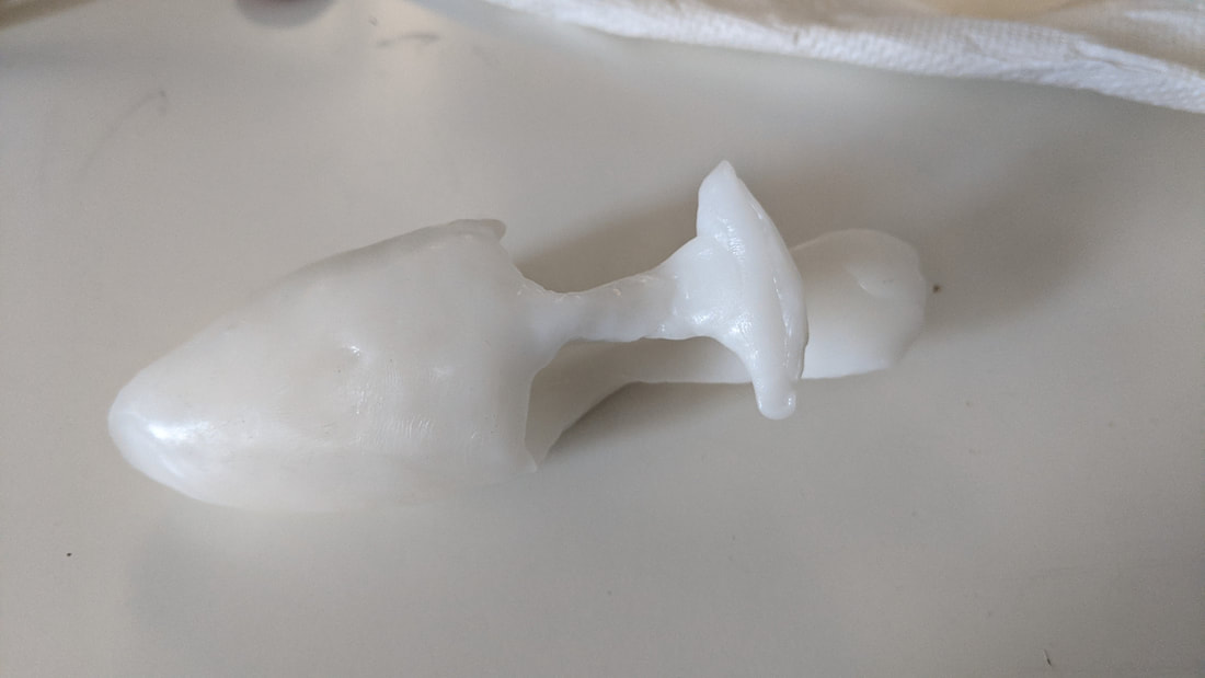
The first two parts printed to test the joint design and flexibility. Unfortunately this design makes it too stiff and the interlocking joint design doesn't have enough allowance to interlock smoothly. I want to work on a new design that finds a middle ground between these two attempts. The circular joint of the last design works perfectly and glues strongly so I will incorporate that in the next model.
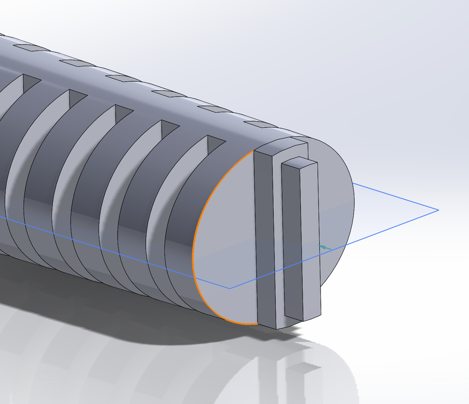
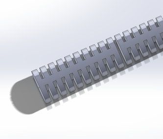
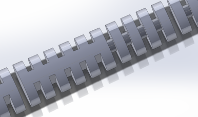
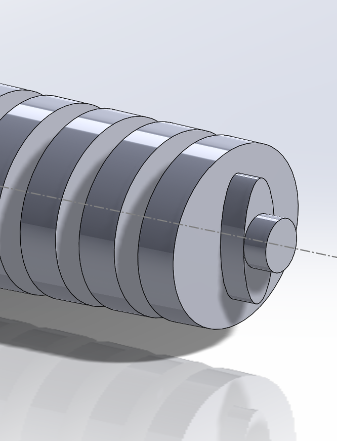
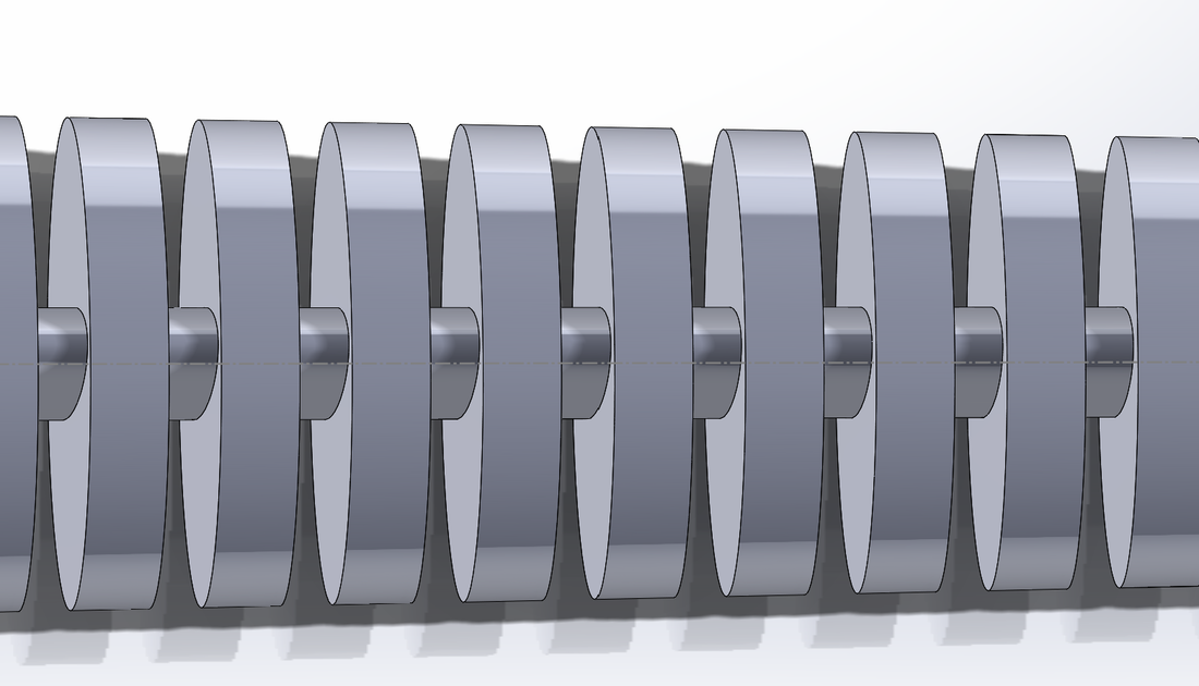
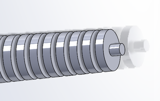
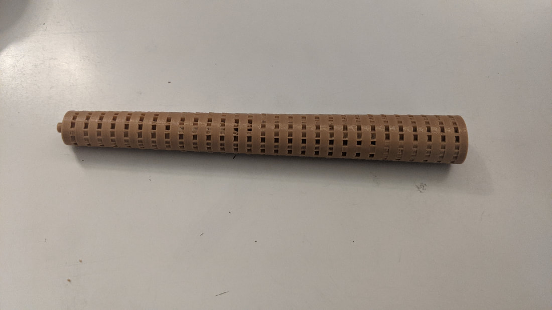
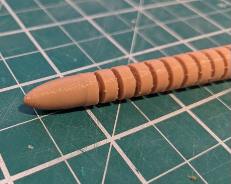
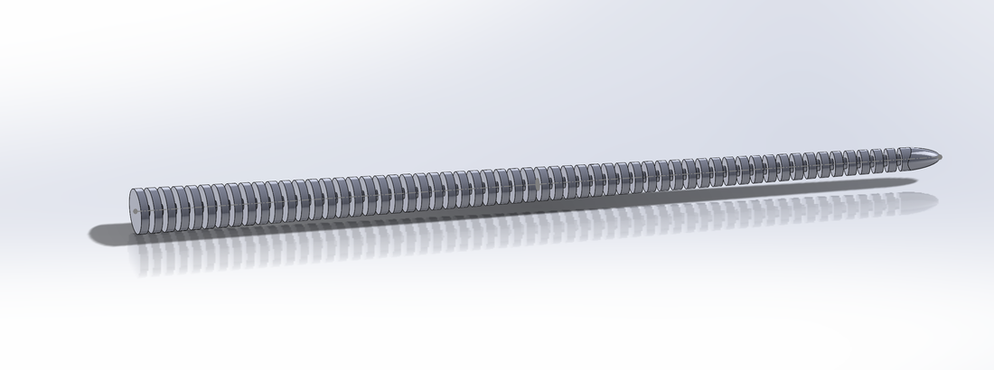
Design 3Here is the model for the third attempt at the tail design. I chose to use a oval shape at the beginning tapering down into the very flexible round centre.
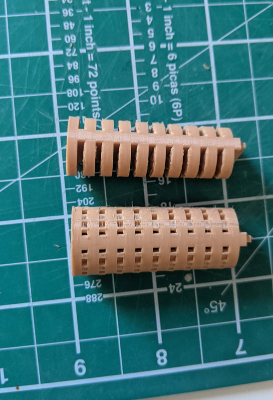
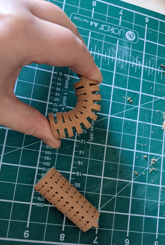
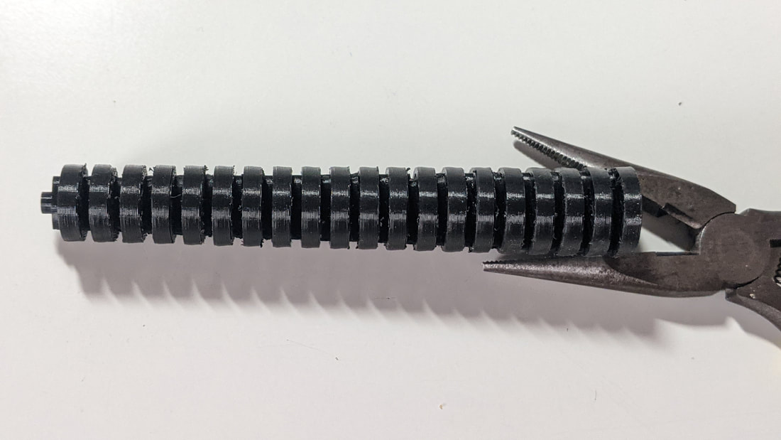
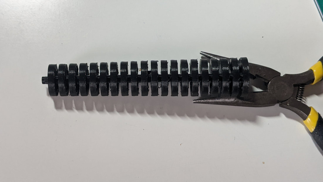
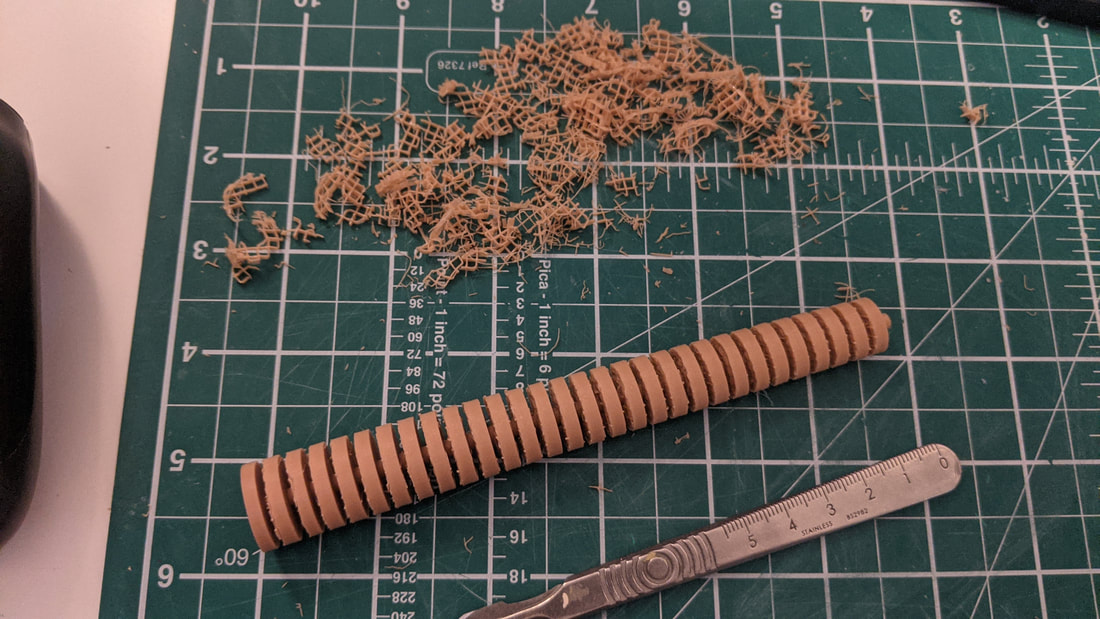
Here are some test prints of this new design in the same TPU filament but in black as it is a experimental print just to see if the movement and joint design works as intended.
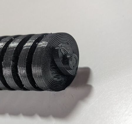
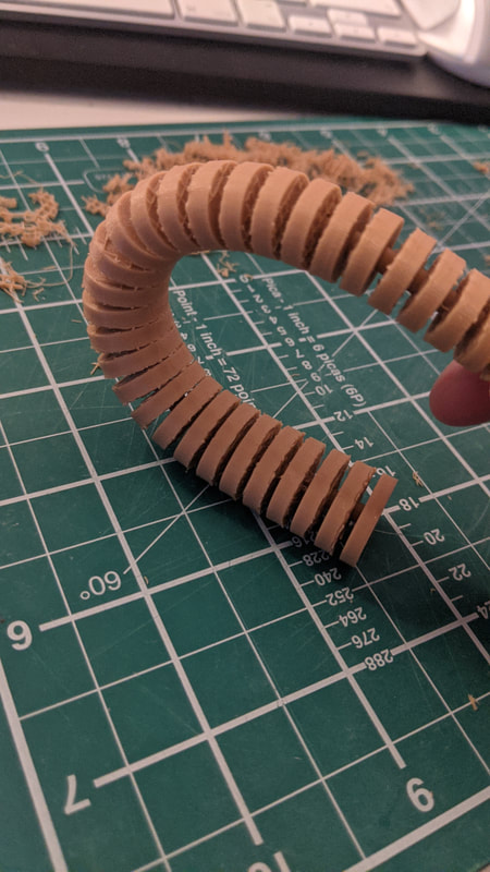
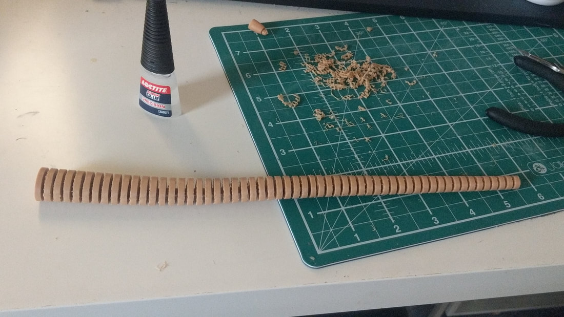
The flexibility of this design is perfect - it has the movement side to side as desired but not up and down. The joint mechanism is shown glued below and is a success! Image coming...
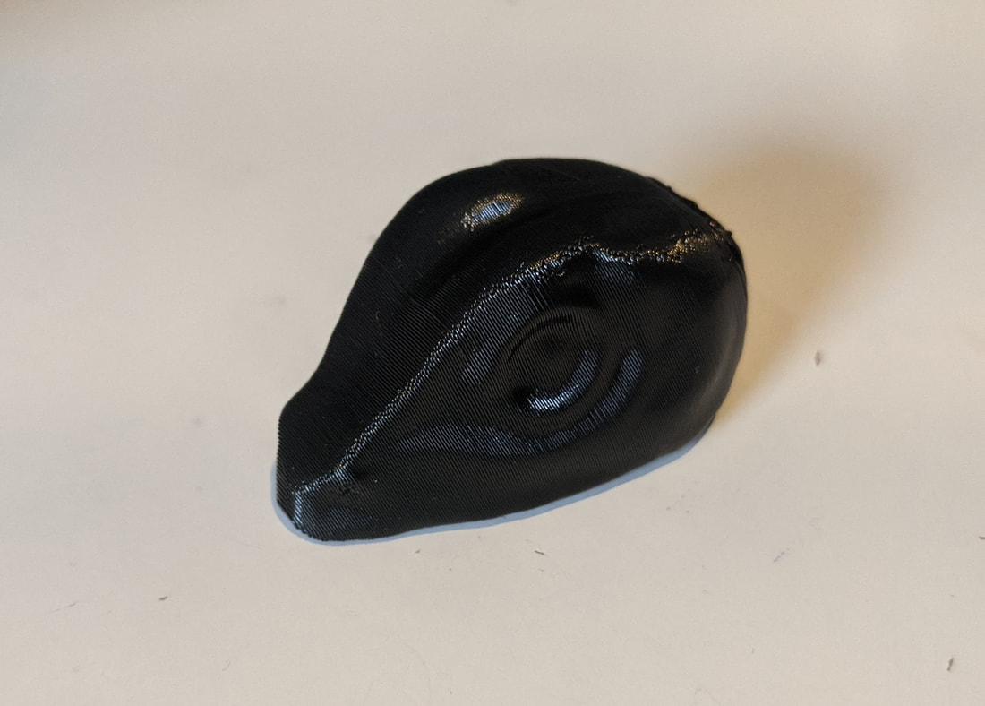
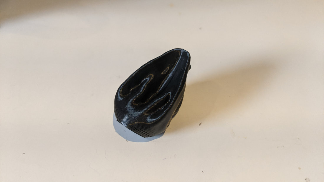
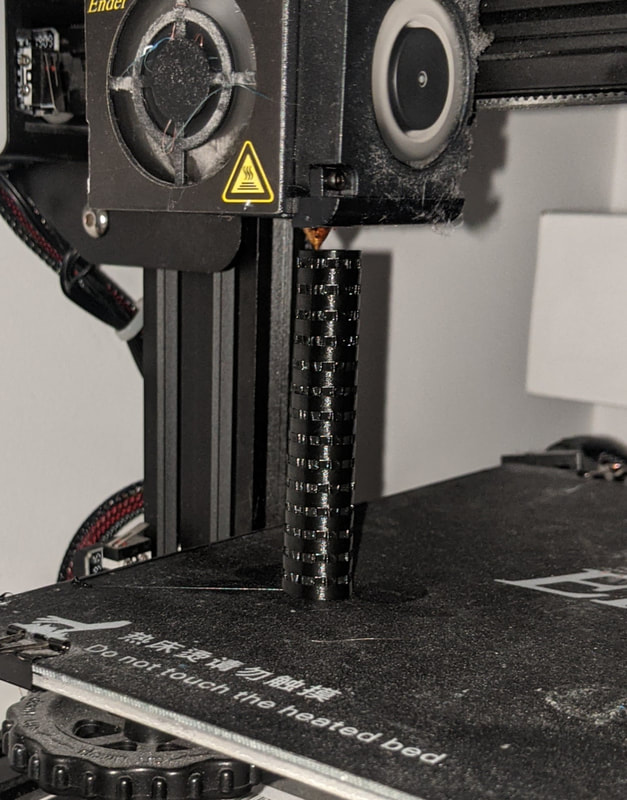
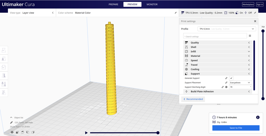
 3D modelled and printed tail experimentThis model was important to see how the printer handled the flexible filament. I had to set up the print vertically so the flat face was on the print bed: I learned that I love how flexible the result is but the printer doesn't. As the print gets closer to the top the TPU filament wobbles and effects print quality. To solve this I now know I need to print in even smaller sections to help with stability.
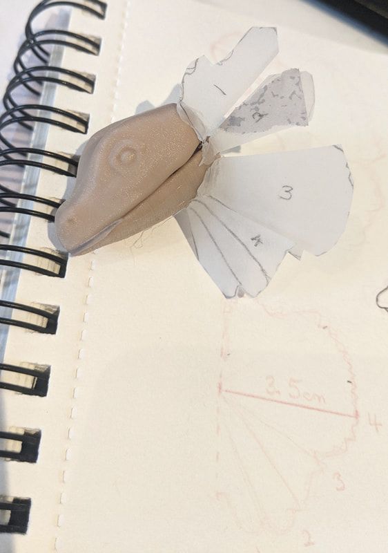
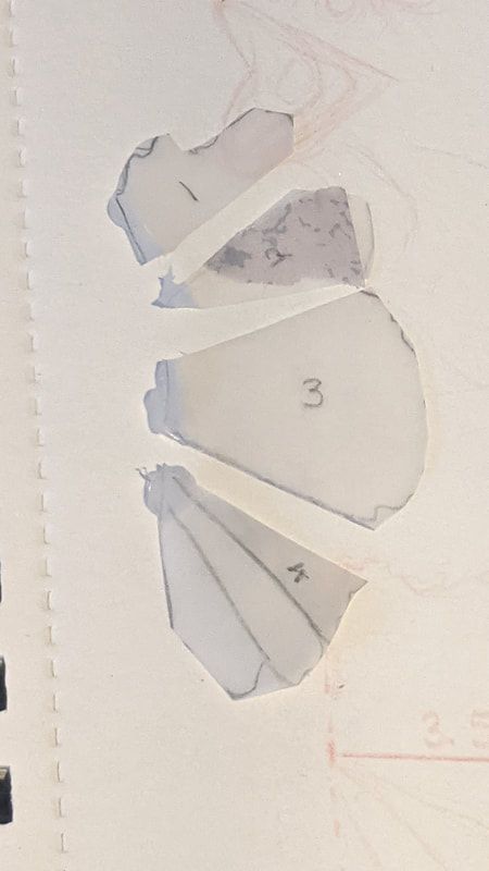
Further Sketches....Left sketches of the frill design and two test print samples using the same filament but at 1mm and 0.5mm thickness. The 1mm was too thick to be soft and flexible, the 0.5mm had a good softness - I want to digitally model and print the frill design as is to see how it moves and folds at this point. Right a new tail design and side profile of the puppet. The tail test print I found too flexible and lacked the control for the puppet: to solve this I am going to...
|